
Journey FWD V6-3.5L (2009)
Clockspring Assembly / Spiral Cable: Description and Operation
Clockspring - Description
DESCRIPTION
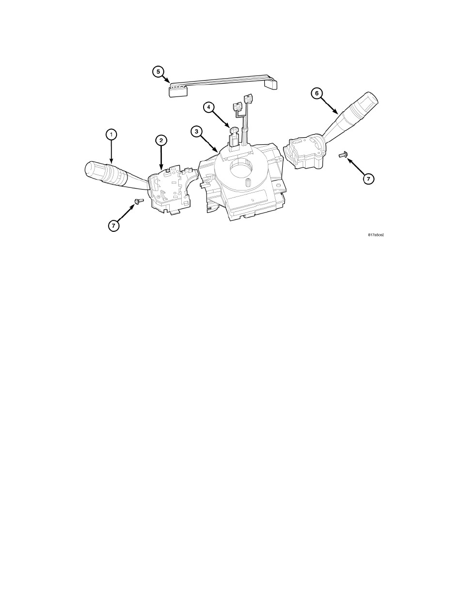
The clockspring (3) for this vehicle is secured near the top of the steering column below the steering wheel. The clockspring also includes an integral,
internal turn signal cancel cam and a Steering Angle Sensor (SAS) that are both serviced as a unit with the clockspring. The clockspring also supports the
left (lighting) multi-function switch (1), the Steering Control Module (SCM) internal to the left multi-function switch housing (2), and the right (wiper)
multi-function switch (6). Each of these switches and the jumper wire harness (5) between the two multi-function switches can be separated from and are
serviced individually from the clockspring.
The clockspring case includes integral tabs for mounting the unit with three screws to the steering column lock housing as well as integral provisions for
mounting and supporting both multi-function switches. The multi-function switches are each secured to the clockspring with a single screw (7). The SAS
within the clockspring includes an electronic circuit board and a microprocessor, which allows it to communicate with other electronic modules in the
vehicle over the Controller Area Network (CAN) data bus. The SAS circuitry, the clockspring, and the turn signal cancel cam are all contained within a
flat, molded plastic case.
The clockspring case includes three connector receptacles that face toward the instrument panel. Within the plastic case is a spool-like molded plastic
rotor with a large exposed hub. The upper surface of the rotor hub has a large center hole, two short pigtail wires with connectors, and a connector
receptacle that faces toward the steering wheel. The lower surface of the rotor has an integral dowel or drive pin that also faces toward the steering
wheel. Wound around the rotor spool within the case is a long ribbon-like tape that consists of several thin copper wire leads sandwiched between two
thin plastic membranes. The outer end of the tape terminates at two of the connector receptacles that face the instrument panel, while the inner end of the
tape terminates at the pigtail wires and connector receptacle on the hub of the clockspring rotor that face the steering wheel. The outer surface of the
rotor hub rim within the clockspring case also has the integral lobes of the turn signal cancel cam.
The service replacement clockspring is shipped pre-centered and with a molded plastic locking pin (4) installed. The locking pin secures the centered
clockspring rotor to the clockspring case during shipment and handling, but must be removed after the clockspring is installed on the steering column and
the steering wheel is installed. See: Service and Repair/Procedures.
The clockspring cannot be repaired. If the clockspring is ineffective, damaged, or if the driver airbag has been deployed, the clockspring/turn signal
cancel cam/SAS unit must be replaced.