
Magnum V6-2.7L VIN T (2007)
Engine Control Module: Description and Operation
Module-Engine Control
Description
DESCRIPTION
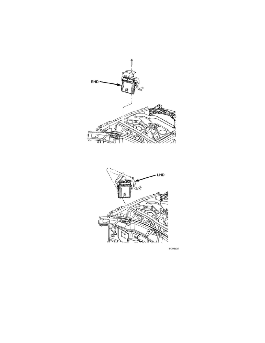
The ECM is located in the left side of engine compartment attached to the left inner fender behind the battery.
The electrical circuits at the ECM are split into two separate wiring harnesses (vehicle and engine wiring harness). The 58-pin connector is used for the
vehicle wiring harness. The 96-pin connector is for the engine wiring harness.
The ECM connectors use slide locks. To remove the ECM connectors, pull the slide locks sideways to the end of their travel and lift the connectors.
A 32-bit microprocessor uses control algorithms to process the input signals and calculates the injected fuel based on stored maps. The microprocessor
triggers the driver stages for switching the output components. The ECM contains the following data storage elements:
1. Flash EPROM-stores engine-specific curves, engine-management maps, and variant coding (engine and equipment options).
2. EEPROM-stores immobilizer data, calibration and manufacturing data, adaptation values, operational faults and variant coding.
3. RAM-stores variable data such as calculations data and input values.