
Magnum V8-5.7L VIN H (2005)
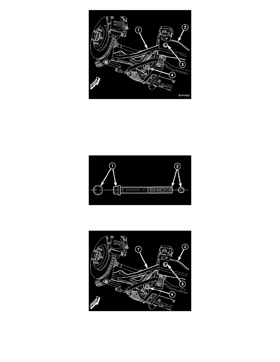
14. Remove bolt (3) and nut securing forward end of lower control arm (1) to engine cradle (2). If bolt has a lengthwise grooved shaft (see above
note), remove bolt and nut by holding bolt stationary with a wrench, removing nut, then sliding bolt out of bushing and cradle while taking note of
bolt positioning in engine cradle for reassembly purposes.
15. Remove bolt and nut (4) securing rearward end of lower control arm (1) to engine cradle (2). If bolt has a lengthwise grooved shaft (see above
note), remove bolt and nut by holding bolt stationary with a wrench, removing nut, then sliding bolt out of bushing and cradle while taking note of
bolt positioning in engine cradle for reassembly purposes.
16. Slide lower control arm (1) from engine cradle (2) and knuckle, and remove from vehicle.
INSTALLATION
NOTE: If installing a lower control arm engine cradle bolt that is a wheel alignment adjustment bolt (1) (identifying lengthwise grooved shaft
(2)), make sure to install it in the same position which it was in upon removal. For more details on installation of this special bolt, (Refer to -
SUSPENSION/ WHEEL ALIGNMENT - STANDARD PROCEDURE).
1. Slide lower control arm (1) into position in engine cradle (2) and place ball joint stem into mounting hole in knuckle.
NOTE: When installing lower control arm engine cradle bolts, it important to note that the forward bolt is installed front-to-rear and the rearward
bolt is installed rear-to-front.
2. Install lower control arm mounting bolts and nuts (3 and 4). Do not tighten bolts at this time.