
Magnum SRT-8 V8-6.1L VIN 3 (2006)
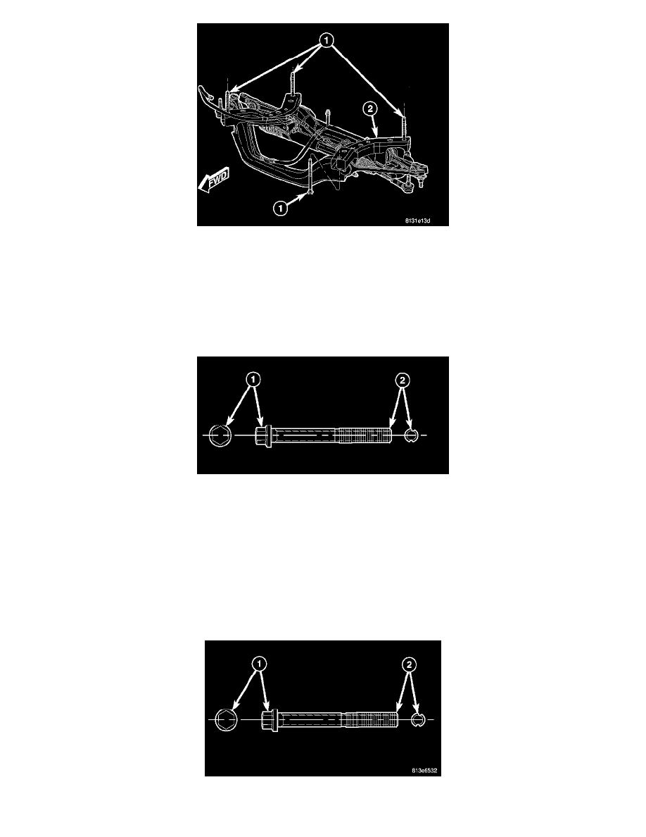
1. Loosen the four bolts (1) fastening the engine cradle (2) to the frame just enough to allow movement of the cradle.
2. Shift cradle as necessary to bring camber or caster into specifications. When shifting cradle, use care not to move other angles (camber or caster)
that are within specifications, out of specifications.
3. Tighten the four bolts (1) fastening the engine cradle (2) to the frame to specifications.
4. Jounce the rear, then front of the vehicle an equal amount of times.
5. Measure camber and caster. If camber and caster are within specifications, proceed to TOE. If camber or caster cannot be brought into
specifications, perform the ADJUSTMENT BOLT PACKAGE INSTALLATION below.
ADJUSTMENT BOLT PACKAGE INSTALLATION - AWD
NOTE: Adjustment bolts for AWD and RWD are not interchangeable.
The adjustment bolt package contains 2 special bolts (1). These bolts can be identified by the offset grooves cut into the thread section (2). These bolts
are designed to replace the inboard mounting bolts of the lower control arm at the engine cradle. Each bolt allows approximately 0.3 degrees of
movement. To adjust camber only, use both bolts, one at each leg of the control arm. To adjust caster only, use one bolt at the front leg only.
1. Raise the vehicle by the frame until the tires are not supporting the weight of the vehicle.
2. Remove the belly pan as necessary.
3. Lower control arm rear bolt only:
a. Remove the screws fastening the heat shields covering the steering gear inner tie rod boots. Remove the heat shields.
b. Loosen (do not remove) the steering gear mounting bolt furthest from the side of adjustment bolt installation.
c. Remove the two remaining steering gear mounting bolts and allow steering gear to relax on the side of adjustment bolt installation, giving
access to the lower control arm rear mounting bolt.
CAUTION: Wheel alignment adjustment bolts have offset grooves cut into the length of the bolt (2). If removing or installing lower control