
Magnum SRT-8 V8-6.1L VIN 3 (2006)
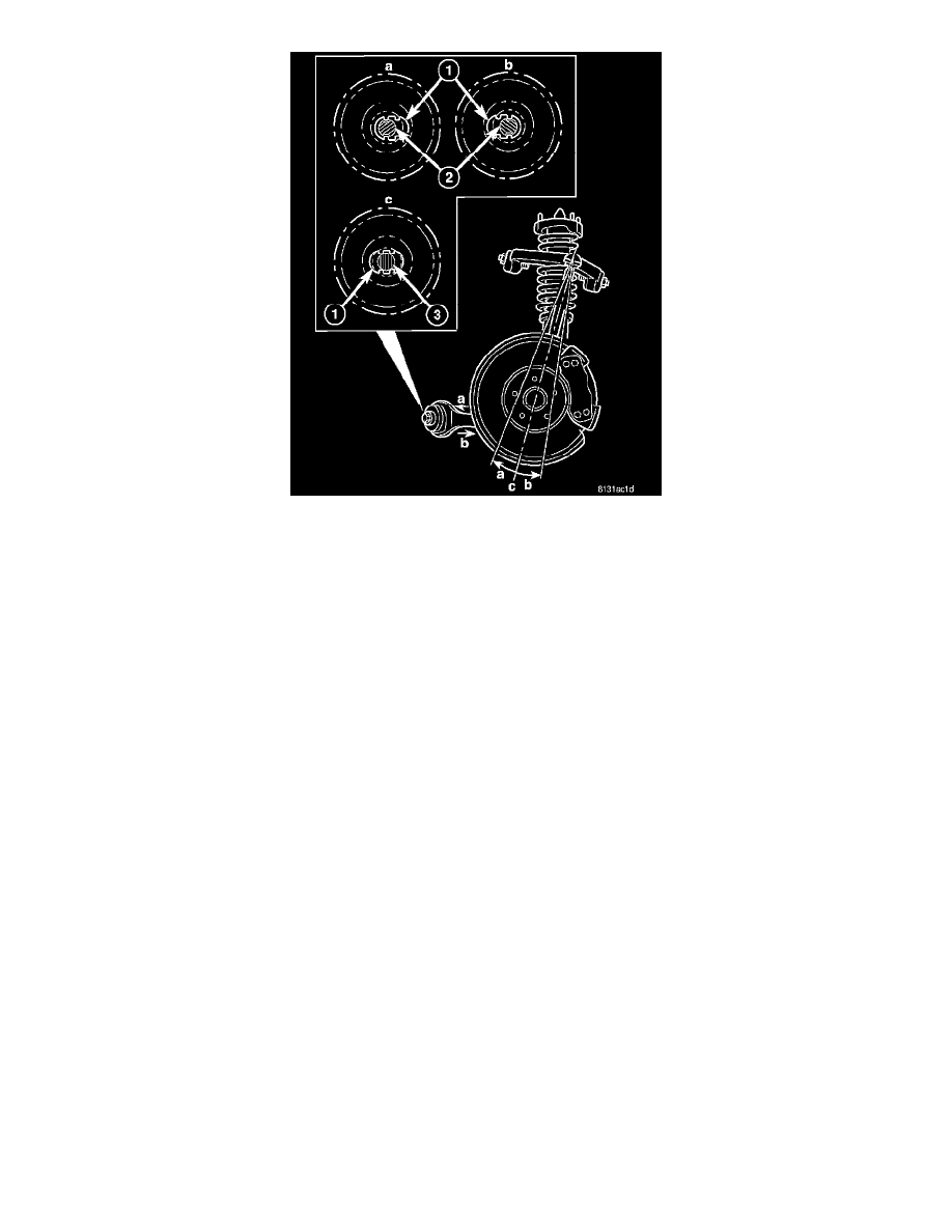
NOTE: The original (non-grooved) mounting bolt (3) lies through the center of the hole (1), between the bat wings ©.
6. Caster Adjustment - The adjustment bolts are designed to work in conjunction with bat wings that are formed into the engine cradle (1) allowing
for tension strut movement approximately 0.30 in either direction.
^
To achieve more positive caster, refer to (a) in the figure. Move the tension strut in the desired direction, then insert the adjustment bolt (2)
with a washer installed through the bat wing hole in the engine cradle (1) and the round hole in the bushing inner metal.
^
To achieve more negative caster, refer to (b) in the figure. Move the tension strut in the desired direction, then insert the adjustment bolt (2)
with a washer installed through the bat wing hole in the engine cradle (1) and the round hole in the bushing inner metal.
7. Start a NEW nut and a washer (on RWD vehicles) on the end of the mounting bolt by hand, then while holding the head of the bolt stationary,
install the nut. Do not tighten the nut at this time.
8. Lower the vehicle to curb position. Jounce the rear, then the front of the vehicle an equal amount of times.
9. Using a crowfoot wrench, tighten the adjustment bolt nut to 176 Nm (130 ft. lbs.) torque while holding the bolt stationary
10. Lower control arm adjustment bolt only - Reinstall the stabilizer bar and heat shields.
11. Measure camber and caster. If camber and caster are not within specifications, inspect the suspension components for any signs of damage or
bending. If camber and caster (and cross-camber and cross-caster) are within specifications, proceed with TOE to check and adjust toe.
12. Install the belly pan.
TOE
1. Center the steering wheel and lock in place using a steering wheel clamp.
NOTE: When performing the toe adjustment procedure, set rear toe to specifications before setting front toe.
2. If rear toe is not within specifications, perform the REAR TOE procedure below.
3. If front toe is not within specifications, perform the FRONT TOE procedure below.
4. Remove the steering wheel clamp.
5. Remove the alignment equipment.
6. Road test the vehicle to verify the steering wheel is straight and the vehicle does not wander or pull.
REAR TOE
NOTE: Perform the following procedure to each side of the vehicle as necessary.