
Monaco V6-182 3.0L SOHC (1990)
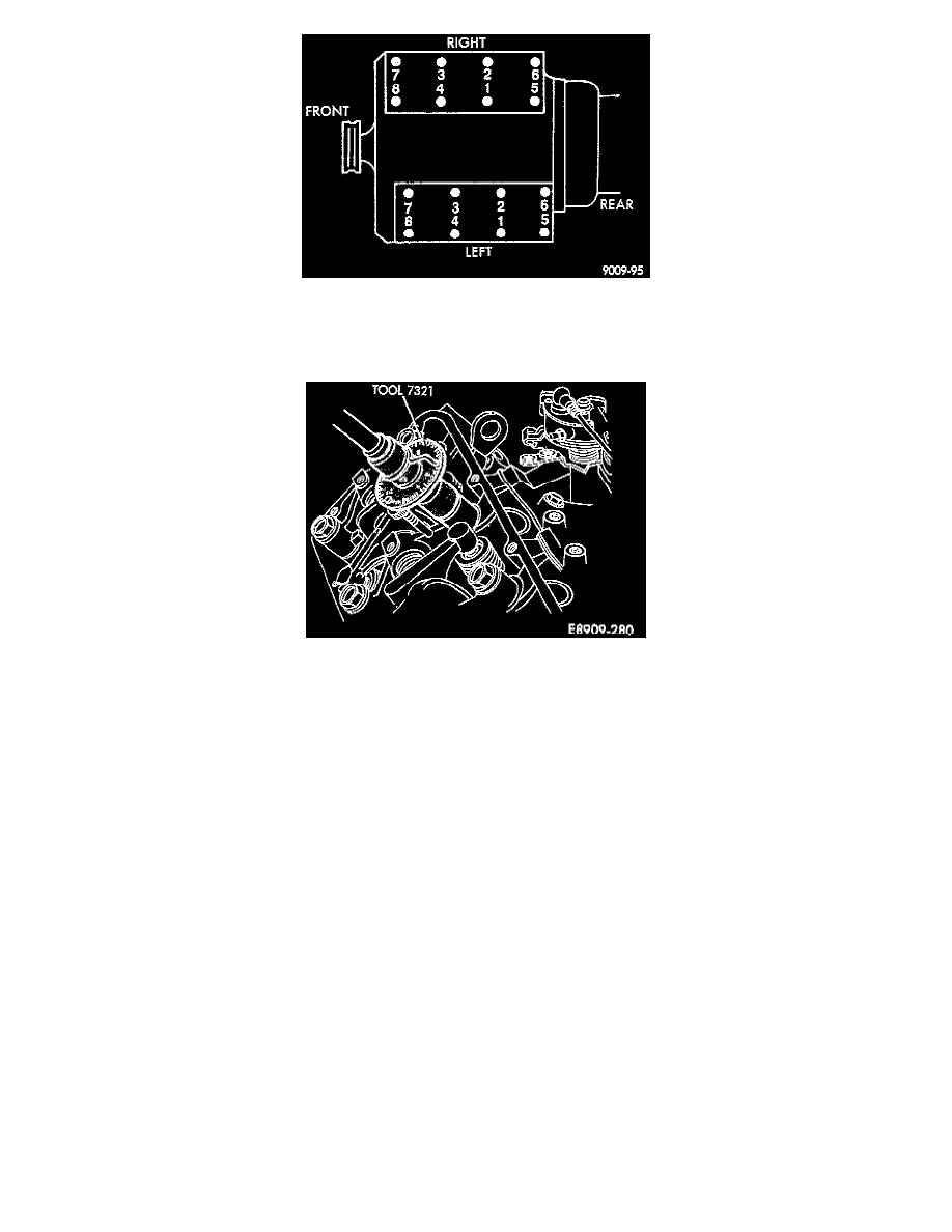
Fig. 12 Cylinder Head Bolt Tightening Sequence
14. Tighten the cylinder head bolts in the sequence shown Fig. 12.
15. Starting with bolt No. 1, pre-tighten all bolts to 60 Nm (44 ft.lbs.) torque.
Fig. 24 Graduated Disc For Angular Tightening
16. The following is performed on all bolts, one bolt at a time.
a
Starting with bolt No.1, loosen the bolt completely.
b
Tighten bolt No. 1 to 40 Nm (30 ft.lbs.) torque.
c
Place graduated disc between the socket and the torque wench Fig. 24.
d
Turn the graduated disc clockwise until the locking stem rests against a solid object which will prevent the disc from turning.
e
Angle tighten bolt No. 1 to 180° +/- 20°.
f
Repeat the procedure for all bolts in the above sequence.
17. Tighten the timing case cover bolts to 12 Nm (9 ft.lbs.) torque.
18. Tighten the camshaft sprocket bolt to 80 Nm (59 ft.lbs.) torque.
19. Cut off any timing case cover gasket flush with the cylinder head.
20. Install the cylinder head cover(s), exhaust manifold(s) and intake manifold.. See Intake Manifold/Service and Repair. See: Intake
Manifold/Service and Repair
21. Install the distributor cap/rotor/dust shield or DIS ignition coils.
22. Install the spark plug wires.
23. Fill and bleed the cooling system. Refer to Cooling System/Service and Repair, for procedure. See: Cooling System/Service and Repair
24. Connect the battery negative cable.
Right
RIGHT CYLINDER HEAD INSTALLATION (ENGINE INSTALLED)
1. Cut the timing case cover gasket flush with the cylinder head gasket face.
2. Cut sections from new gaskets and attack them to the timing case cover. Apply a thin bead of weather strip adhesive. Allow to dry.