
Neon L4-2.0L DOHC (1996)
Throttle Position Sensor: Description and Operation
Throttle Position Sensor Operation
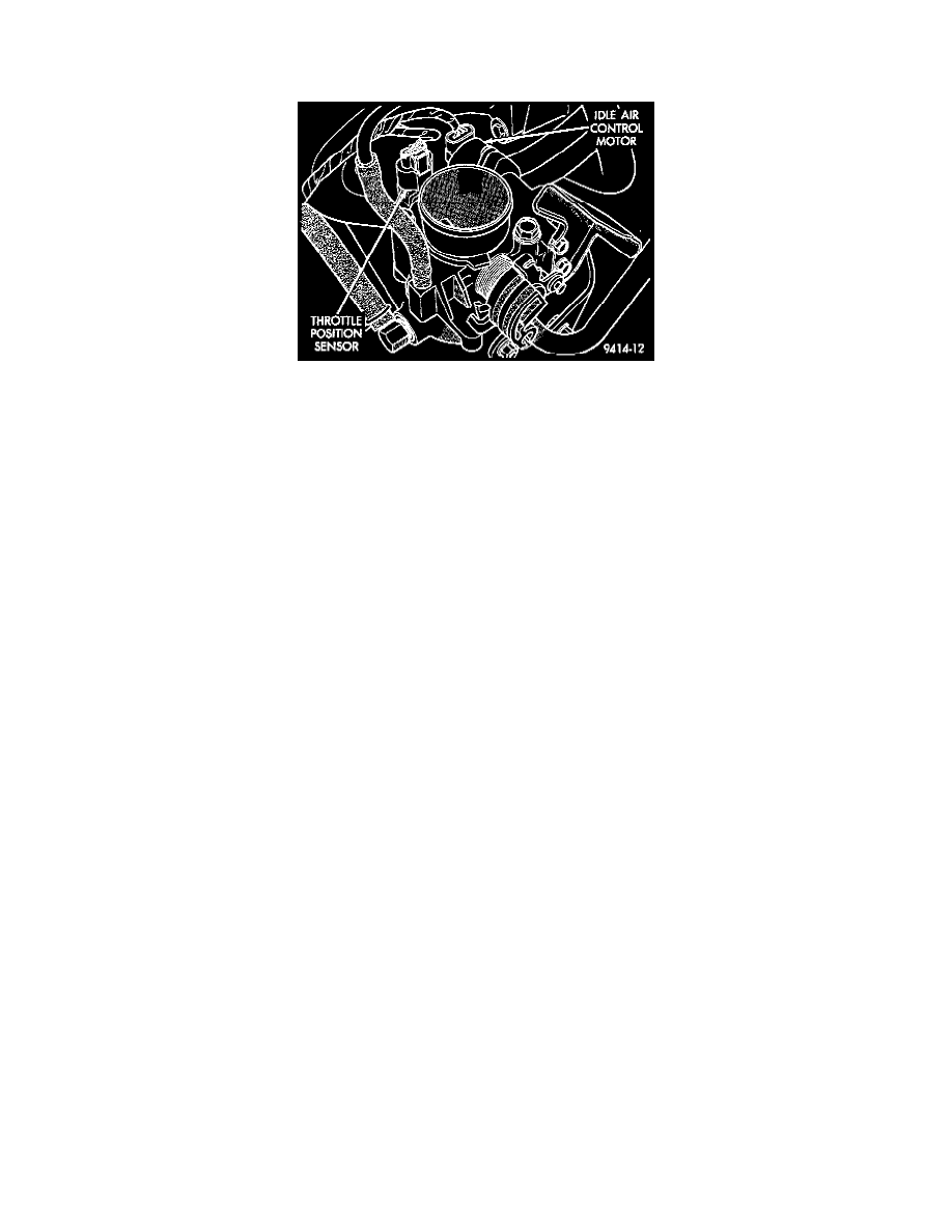
Fig. 16 Throttle Position Sensor And Idle Air Control Motor -- Typical
PURPOSE
Along with inputs from other sensors, the PCM uses the Throttle Position Sensor (TPS) input to determine current engine operating conditions.
The PCM also adjusts fuel injector pulse width and ignition timing based on these inputs.
OPERATION
The TPS mounts to the throttle body and connects to the throttle blade shaft.
The TPS is a variable resistor that provides the PCM with an input signal (voltage).
-
The signal represents throttle blade position.
-
As the position of the throttle blade changes, the resistance of the TPS changes.
The PCM supplies approximately 5 volts DC to the TPS. The TPS output voltage (input signal to the powertrain control module) represents
throttle blade position.
The TPS output voltage to the PCM varies:
-
At minimum throttle opening (idle) -- from 0.38 to 1.03 volts.
-
AT Wide open throttle -- 3.1 to 4.0 volts.
The throttle position sensor mounts to the side of the throttle body (Fig. 16).
CIRCUIT OPERATION
From the Powertrain Control Module (PCM) circuit K6 supplies 5 Volts to the Throttle Position Sensor (TPS). Circuit K6 connects to cavity 61
of the PCM connector.
Circuit K22 delivers the TPS signal to the PCM. Circuit K22 connects to cavity 35 of the PCM connector.
The PCM provides ground for the TPS signal (circuit K22) through circuit K4. Circuit K4 connects to cavity 43 of the PCM connector.