
Neon L4-2.0L DOHC (1996)
Fuel Gauge Sender: Description and Operation
General Description
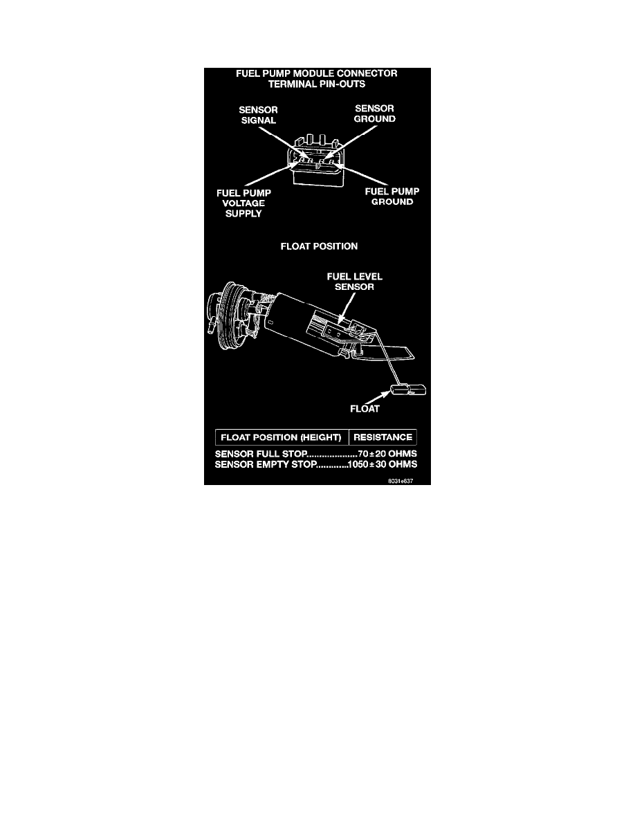
Fig. 10 Level Sensor Diagnosis
OPERATION
The fuel gauge sending unit is attached to the side of the fuel pump module. The sending unit consists of a float, an arm, and two variable resistors
(tracks). These two tracks are used to send two different electrical signals. One is used for fuel gauge operation and the other is for OBD II
emission requirements.
Track 1 fuel gauge operation: As the fuel level increases, the float and arm move up. This decreases the sending unit resistance, causing the fuel
gauge on the instrument panel to read full. As the fuel level decreases, the float and arm move down. This increases the sending unit resistance,
causing the fuel gauge on the instrument panel to read empty
Track 2-OBD II emission requirements: A variable voltage signal is sent to the PCM to indicate fuel level. The purpose of this feature is to
prevent a false setting of misfire and fuel system monitor trouble codes if the fuel level in the tank is less than 15 percent of its rated capacity.