
Neon L4-2.0L SOHC (1995)
Ignition Cable: Component Tests and General Diagnostics
Testing
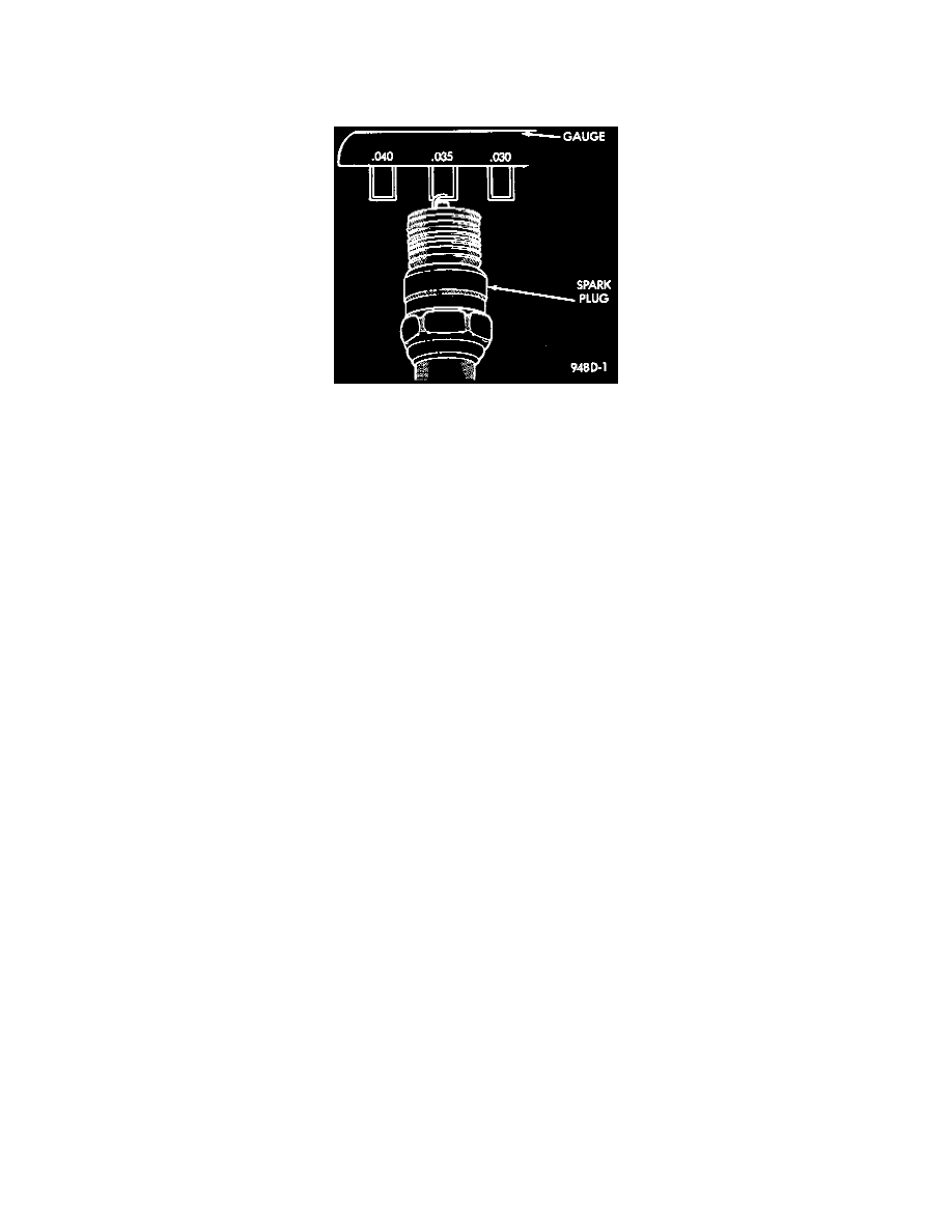
Fig. 4 Setting Spark Plug Electrode Gap
TESTING USING AN OSCILLOSCOPE
When testing cables for punctures and cracks with an oscilloscope, follow the instructions of the equipment manufacturers.
CAUTION: Do not leave any one spark plug cable disconnected any longer than necessary during test or possible heat damage to catalytic converter
will occur. Total test time must not exceed one minute.
NOTE: Test must be performed at idle only.
IF AN OSCILLOSCOPE IS NOT AVAILABLE, TEST CABLES AS FOLLOWS:
1. With the engine not running, connect one end of a test probe (i.e. a piece of wire with insulated alligator clips on each end) to a good ground, other
end free for probing.
WARNING: The direct ignition system generates approximately 40,000 volts. Personal injury could result from contact with this system.
2. With engine running, move test probe along entire length of all cables (approximately 0 to 1/8 inch gap). If punctures or cracks are present there
will be a noticeable spark jump from the faulty area to the probe. Cracked, leaking or faulty cables should be replaced.
3. Use an ohmmeter to check cables for opens, loose terminals or high resistance.
a. Remove cable from spark plug.
b. Remove cable from the coil tower.
c. Connect the ohmmeter between spark plug end terminal and the coil end terminal. Resistance should be within tolerance shown in the cable
resistance chart. If resistance is not within tolerance, replace cable assembly. Test all spark plug cables in same manner.
CABLE RESISTANCE CHART
MINIMUM
MAXIMUM
250 Ohms/Inch
1,000 Ohms/Inch
3,000 Ohms/Foot
12,000 Ohms/Foot
Testing For Open Circuits, High Resistance and Loose Terminals
Use an ohmmeter to check cables for opens, loose terminals or high resistance as follows:
1. Remove cable from spark plug.
2. Remove cable from the coil tower.
3. Connect the ohmmeter between the spark plug end terminal and the coil end terminal.
-
Make sure ohmmeter probes are in good contact.
-
Resistance should be within tolerance shown in the cable resistance chart.
-
If resistance is not within tolerance, replace cable assembly. Test all spark plug cables in the same manner.
-
If no problems are found, SEE Ignition System/System Diagnosis/Testing For Spark At Coil.
SECONDARY IGNITION CABLE RESISTANCE
Minimum
Maximum
250 Ohms per Inch
1,000 Ohms per Inch
3,000 Ohms per Foot
12,000 Ohms per Foot