
Neon L4-2.0L VIN C (1998)
Hydraulic Control Assembly - Antilock Brakes: Description and Operation
System Operation
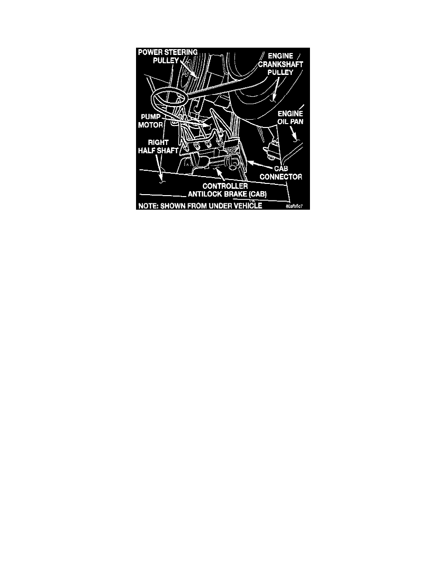
ICU Mounting Location
General Information
The Hydraulic Control Unit (HCU) contains the valve block assembly, two accumulators, and pump/motor assembly. The HCU is located under
the Master Cylinder on the left front frame rail.
Valve Block AssemblY
The valve block assembly contains valves with four inlet valves and four outlet valves. The inlet valves are spring-loaded in the open position and
the outlet valves are spring loaded in the closed position. During and antilock stop, these valves are cycled to maintain the proper slip ratio for
each wheel. If a wheel detects slip, the inlet valve is closed to prevent and further pressure increase. Then the outlet valve is opened to release the
pressure to the accumulators until the wheel is no longer slipping. Once the wheel is no longer slipping, the outlet valve is closed and the inlet
valve is opened to reapply pressure. If the wheel is decelerating within its predetermined limits (proper slip ratio), the inlet valve will close to hold
the pressure constant. On JX and NS Bodies which are equipped with a traction control system, there are two additional valves that isolate the
master cylinder and rear wheels. During a traction control situation the brakes are applied to reduce wheel slippage.
Pump/Motor Assembly
The pump/motor assembly provides the extra amount of fluid needed during antilock braking. The pump is supplied fluid that is released to the
accumulators when the outlet valve is opened during and antilock stop. The pump is also used to drain the accumulator circuits after the antilock
stop is complete. The pump is operated by an integral electric motor. This DC-type motor is controlled by the Control Antilock Brake (CAB). The
CAB may turn on the pump motor when an antilock stop is detected. The pump continues to run during the antilock stop and is turned off after the
stop is complete. Under some conditions, the pump/motor will run to drain the accumulators during the next drive off. The pump mechanism
consists of two opposing pistons operated by an eccentric camshaft secondary hydraulic circuit. In operation, one piston craw fluid from the
accumulators. The opposing piston pumps fluid to the valve body solenoids. The CAB monitors the pump/motor operation internally.
Accumulators
The accumulators provide temporary fluid storage during an antilock stop and are drained by the pump/motor. Each of the diagonal circuits uses a
3cc. accumulator.