
Neon L4-2.0L VIN C (1998)
EGR Control Solenoid: Testing and Inspection
TESTING ELECTRICAL SOLENOID PORTION OF VALVE
This is not to be used as a complete test of the EGR system.
Electrical operation of the valve should be checked with the DRB or equivalent scan tool. Refer to the appropriate procedures. Replace solenoid if
necessary, unit serviced only as an assembly
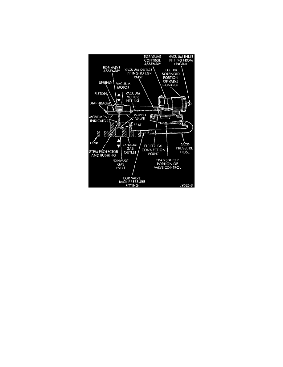
Fig 4 EGR System
TESTING VACUUM TRANSDUCER PORTION OF VALVE
NOTE: The first part of this test will determine if the transducer diaphragm at the back-pressure side of the valve has ruptured or is leaking. The second
part of the test will determine if engine vacuum (full-manifold) is flowing from the inlet to the outlet side of the valve. This is not to be used as a
complete test of the EGR system.
1. Disconnect the rubber back-pressure hose from the fitting at the bottom of EGR valve (Fig. 4).
2. Connect a hand-held vacuum pump to this fitting.
3. Apply 10 inches of vacuum to this fitting.
4. If vacuum falls off, the valve diaphragm is leaking.
5. Replace the Complete EGR valve assembly.
-
Proceed to next step for further testing.
6. Reconnect hose to EGR valve.
7. Remove the vacuum supply hose at the vacuum inlet fitting (Fig. 4) on the EGR solenoid.
8. Connect a vacuum gauge to this disconnected vacuum line.
9. Start the engine and bring to operating temperature. Hold engine speed at approximately 1500 rpm.
10. Check for steady engine vacuum (full-manifold) at this hose.
11. If engine vacuum (full-manifold) is not present, check vacuum line to engine and repair as necessary before proceeding to next step.
12. Reconnect the rubber hose to the vacuum inlet fitting (Fig. 4) on the EGR valve.
13. Disconnect the rubber hose at the vacuum outlet fitting (Fig. 4) on the EGR valve.
14. Connect a vacuum gauge to this fitting.
15. Disconnect the electrical connector (Fig. 4) at the valve control.
-
This will simulate an open circuit (no ground from the PCM) at the valve, activating the valve.
-
A DTC will be set in the PCM that must be erased after testing is complete.
16. Start the engine and bring to operating temperature.
17. Hold the engine speed to approximately 2,000 rpm while checking for engine vacuum (full-manifold) at this fitting.
-
To allow full manifold vacuum to flow through the valve, exhaust back-pressure must be present at valve. It must be high enough to hold the
bleed valve in the transducer portion of the valve closed.
-
Have a helper momentarily (a second or two) hold a rag over the tailpipe opening to build some exhaust back-pressure while observing the