
Neon L4-2.0L VIN C (1998)
Clockspring Assembly / Spiral Cable: Service and Repair
REMOVAL
WARNING: DISCONNECT AND ISOLATE THE BATTERY NEGATIVE (GROUND) CABLE BEFORE BEGINNING ANY AIRBAG
SYSTEM COMPONENT REMOVAL OR INSTALLATION PROCEDURE. THIS WILL DISABLE THE AIRBAG SYSTEM. FAILURE
TO DISCONNECT BATTERY COULD RESULT IN ACCIDENTAL AIRBAG DEPLOYMENT AND POSSIBLE PERSONAL INJURY.
ALLOW SYSTEM CAPACITOR TO DISCHARGE FOR 2 MINUTES BEFORE REMOVING ANY AIRBAG COMPONENTS.
1. Place the front road wheels in the straight ahead position then:
-
Rotate the steering wheel half turn (180 °) to the right (clockwise)
-
Lock column with ignition lock cylinder.
2. Disconnect and isolate the battery negative cable.
3. Wait two minutes for the reserve capacitor to discharge before removing non-deployed module.
4. Remove speed control switch mounting screws, switches and disconnect the wire connectors or remove covers.
5. Remove the Driver Airbag Module attaching bolts from under the speed control switches or covers.
6. Lift module and disconnect the airbag and horn wire connectors.
7. Remove the steering wheel, refer to Steering and Suspension/Steering Wheel removal procedures.
8. Remove upper and lower steering column shrouds to gain access to clockspring wiring.
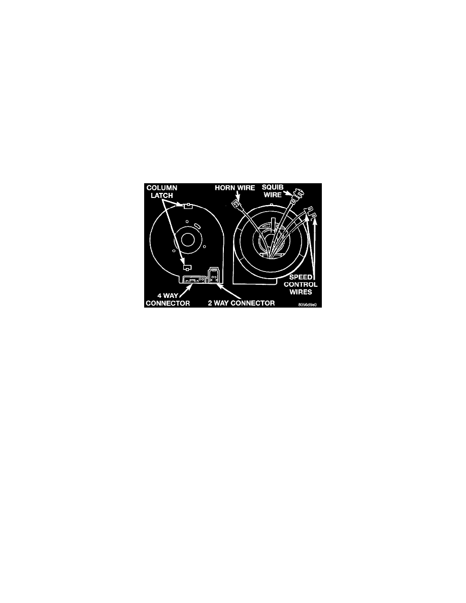
9. Disconnect the 2-way and 4-way connectors between the clockspring and the instrument panel wiring harness at the base of the clockspring.
10. Unlatch and remove clockspring assembly from steering shaft. The clockspring cannot be repaired, and must be replaced if faulty.
11. Rotate clockspring rotor a half turn (180 °) to the left (counter clockwise).
12. Lock the clockspring rotor in the center position as follows: Insert a paper clip wire through the hole in the rotor at the 10 O' Clock position
and bend to prevent it from falling out.
INSTALLATION
1. Confirm that:
-
The steering wheel position is a half turn (180 °) to the right (clockwise)
-
The column is locked with the ignition cylinder lock.
-
Check that the turn signal stalk is in the neutral position
-
When reusing the clockspring, remove locking wire and rotate clockspring rotor one half turn (180 °) to the right (clockwise). Locate the
clock-spring on the steering shaft and push down on the rotor until the clockspring is fully seated on the steering column.
-
When installing a new clockspring remove grenade pin and rotate clockspring rotor one half turn (180 °) to the right (clockwise). Locate
clock-spring on the steering shaft and push down on the rotor until the clockspring is fully seated on the steering wheel.
2. Connect the clockspring to the instrument panel harness, ensure wiring is properly routed. Then check that the connectors, locking tabs are
properly engaged and the halo lamp wire is in position.
3. Install steering column shrouds. Be sure all wires are inside of shrouds.
4. Install steering wheel ensuring the fiats on hub align with the clockspring. Pull the horn, airbag and speed control leads through the larger slot.
Ensure leads do not get pinched under the steering wheel.
5. Route speed control wires under and behind the airbag module mounting tabs.
6. Connect the horn lead wire and the airbag lead wire to the airbag module.
7. Install the airbag module and tighten bolts to 12 to 14 N.m (105 to 125 in. lbs.) torque.
8. Connect the speed control wires to the switches and install switches. Tighten screws to 2 N.m (20 in. lbs.) torque.
9. Do not connect the battery negative cable. Refer to Diagnosis and Testing for Airbag System Test procedures.