
Neon R/T L4-2.0L VIN F HO (2001)
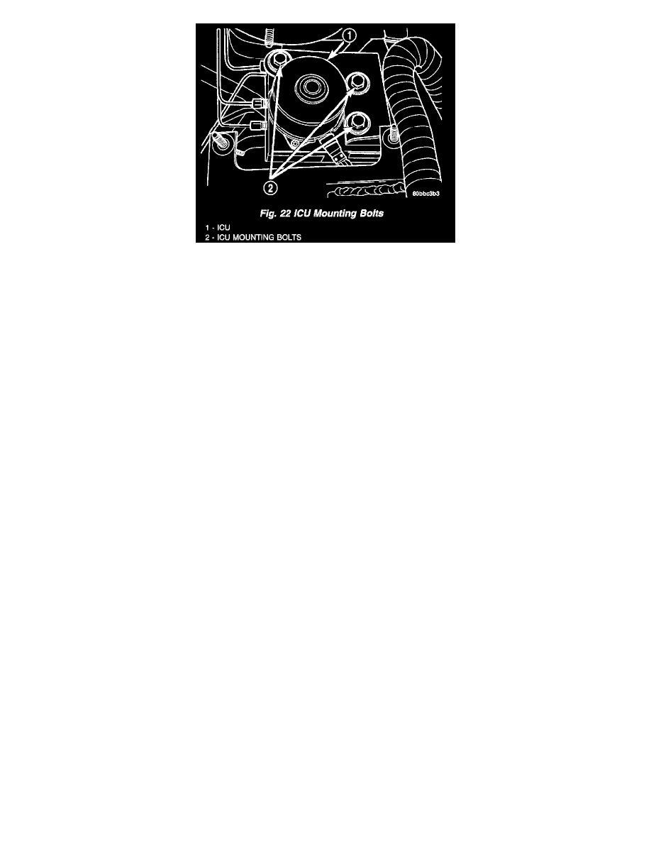
12. Remove the 3 bolts attaching the ICU to its mounting bracket.
13. Remove the ICU from the vehicle.
14. If the CAB and HCU must be separated, Refer to INTEGRATED CONTROL UNIT - DISASSEMBLY.
INSTALLATION - ICU
NOTE: Before proceeding with this procedure, Refer to Service Precautions.
1. Install the Integrated Control Unit (ICU) onto its mounting bracket.
2. Install the 3 bolts attaching the ICU to the mounting bracket. Tighten the 3 mounting bolts to a torque of 11 Nm (97 inch lbs.).
3. Install the four brake tubes going to the brakes into their respective outlet ports on the ICU Hydraulic Control Unit (HCU). Using a crow foot on a
torque wrench, tighten the four brake tube nuts to a torque of 17 Nm (145 inch lbs.).
NOTE: When installing the brake tubes from the master cylinder on the HCU, the brake tube with the small tube nut is to be installed in the
forward-most port on the HCU with the small end going toward the master cylinder secondary port.
4. Install the primary and secondary brake tubes from the master cylinder onto the HCU. Do not completely tighten the primary and secondary tubes
at this time.
5. Connect the primary and secondary brake tubes to the master cylinder ports.
6. Using a crow foot on a torque wrench, tighten the primary and secondary brake tube nuts at both the master cylinder and HCU to a torque of 17
Nm (145 inch lbs.).
CAUTION: Before installing the 25-way connector in the Controller Antilock Brake (CAB), be sure the seal is properly installed in the
connector.
7. Install the 25-way connector into the socket of the CAB as follows:
-
Position the 25-way connector in the socket of the CAB and carefully push it down as far as possible.
-
When the connector is fully seated into the CAB socket, push the connector lock inward. This pulls the connector into the socket of the CAB
and locks it in the installed position.
8. Position the battery tray back in place. Install the two bolts, then the two nuts mounting the battery tray to its bracket. Tighten the two bolts and
nuts to a torque of 15 Nm (135 inch lbs.).
9. Reinstall the air cleaner box onto its grommeted alignment post.
10. Install the one nut and one bolt securing the air cleaner box in place, then connect the wiring harness connector at the air inlet sensor.
11. Install the battery and clamp it in place. Tighten the hold-down clamp bolt to a torque of 12 Nm (106 inch lbs.).
12. Connect the positive, then the negative (ground) cable on the battery.
NOTE: The ICU may need to be initialized using the DRBIII scan tool after ICU installation. Refer to Appropriate Diagnostic Information.
13. Bleed the base brakes and Antilock Brake System (ABS) hydraulic systems.
14. Fill the master cylinder to the proper fill level.
15. Road test the vehicle to ensure proper operation of the base and ABS.