
Neon R/T L4-2.0L VIN F HO (2001)
Clutch Switch: Testing and Inspection
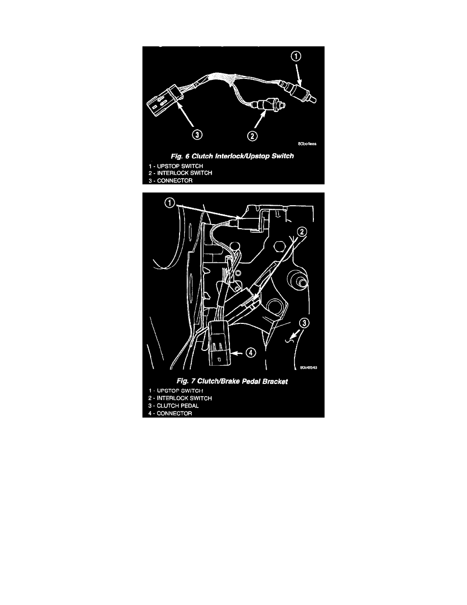
CLUTCH INTERLOCK/UPSTOP SWITCH
The clutch interlock/upstop switch is an assembly consisting of two switches: an engine starter inhibit switch (interlock) and a clutch pedal upstop
switch (Fig. 6). The switch assembly is located in the clutch/ brake pedal bracket assembly (Fig. 7), each switch being fastened by four plastic wing
tabs.
CLUTCH INTERLOCK SWITCH
Mechanical Test
1. With the park brake set and the transaxle IN NEUTRAL, turn the ignition key to the start position. The engine starter should not crank with the
clutch pedal at rest (not depressed). If the starter cranks, proceed to the electrical test to determine whether the switch is defective or the circuit is
shorted. If the vehicle does not crank, proceed to the next step.
2. With the park brake set and the transaxle IN NEUTRAL, fully depress the clutch pedal and turn the ignition key to the start position. The engine
starter should crank. If the starter does not crank, visually inspect the clutch pedal for obstructions (floor mat, etc.) and for proper installation of
the master cylinder push rod/bushing on the pedal pin. Also make sure the clutch pedal blade contacts and fully closes the switch.
Electrical Test
1. Move ignition key to the "OFF/LOCK" position and remove key.
2. Set park brake.
3. Disconnect the clutch interlock/upstop switch connector.
4. Using an ohmmeter, check for continuity between terminals 2 & 3 with the interlock switch not depressed (clutch pedal at rest). There should be