
Neon R/T L4-2.0L VIN F HO (2001)
1. Install switches into the pedal bracket assembly as shown in (Fig. 11). Route harness as was prior to removal.
2. Install clutch and brake pedals to pedal bracket, and install pivot shaft and nut. Torque pivot shaft nut to 34 Nm (25 ft. lbs.).
3. Install brake/clutch pedal bracket assembly into position. Install and tighten brake booster mounting nuts to 34 Nm (25 ft. lbs.). Install and tighten
pedal bracket-to-instrument panel nuts to 34 Nm (25 ft. lbs.).
4. Install new stop lamp switch.
5. Connect brake booster rod to brake pedal. Install retainer clip (Fig. 9).
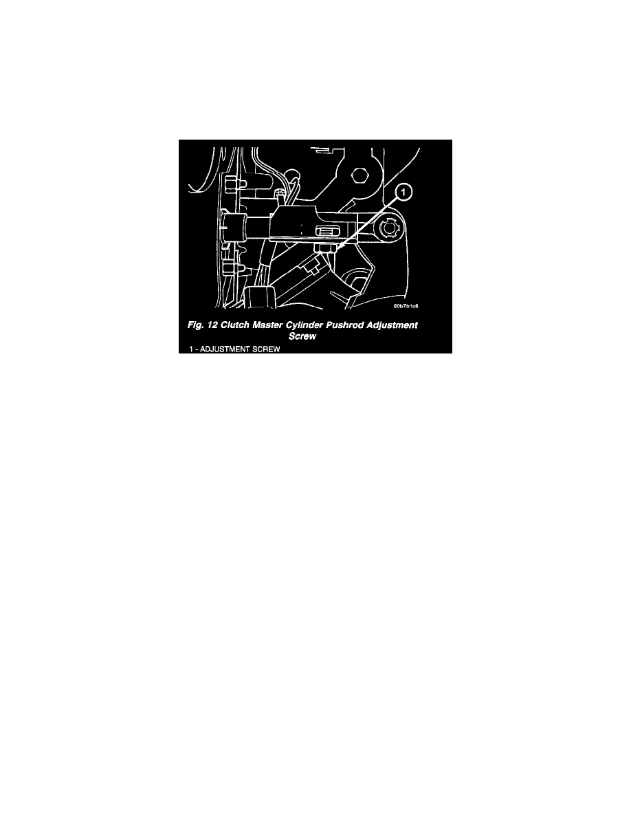
CAUTION: Inspect clutch master cylinder pushrod plastic retainer. If retainer is damaged in any way (broken/cracked) it MUST be replaced.
6. Connect clutch master cylinder pushrod. Loosen adjustment screw (Fig. 12) and gently lift clutch pedal upwards until the clutch pedal fully
depresses the the upstop switch. Torque adjustment screw to 8 Nm (70 inch lbs.).
7. Connect interlock/upstop and stop lamp switch connectors.
8. Install left lower instrument panel bezel (Fig. 8).
9. Connect battery negative cable.
10. Verify proper switch operation.