
Neon R/T L4-2.0L VIN F HO (2001)
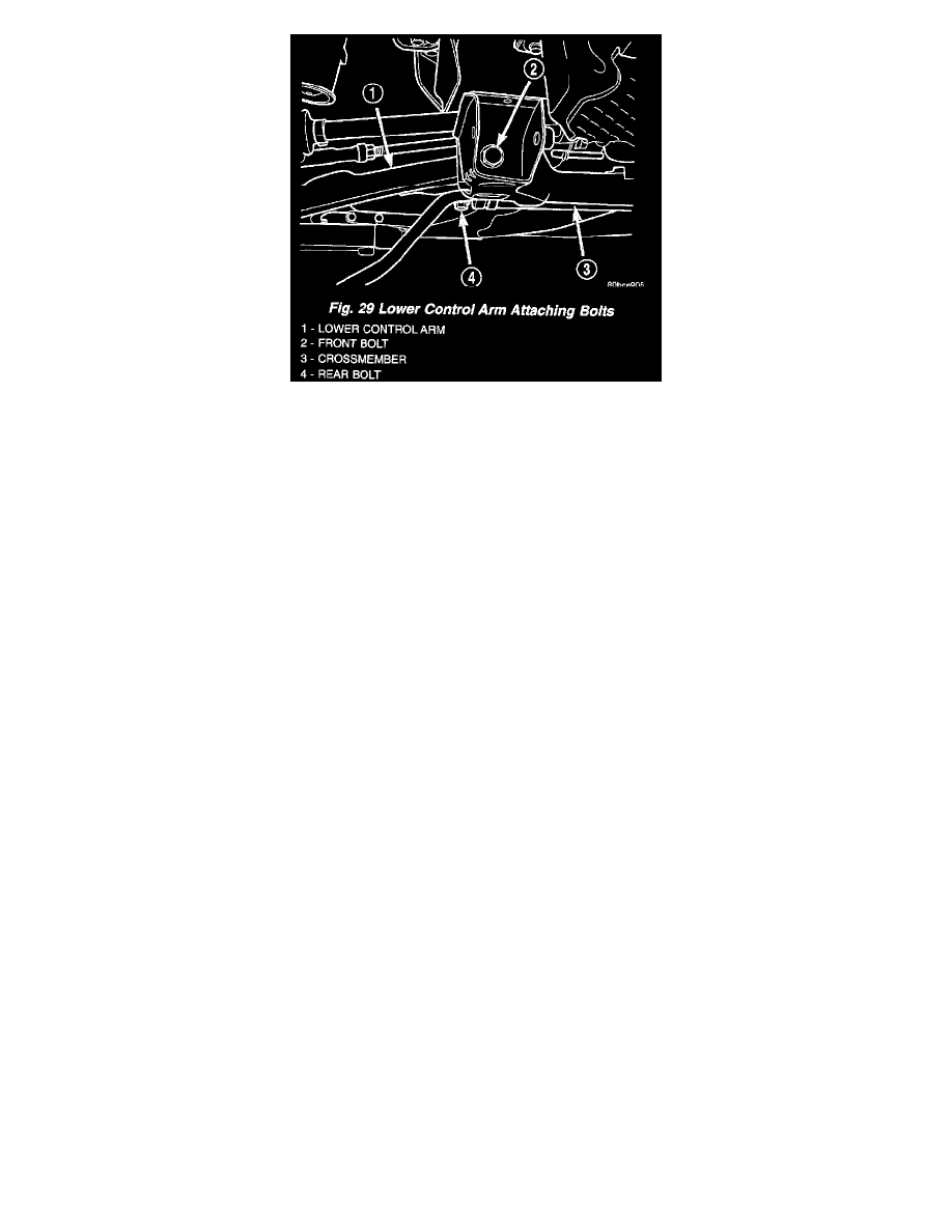
8. Remove the front pivot bolt attaching the lower control arm to the front suspension crossmember. Remove the rear pivot bolt attaching the lower
control arm to the front suspension crossmember and frame rail. Remove the lower control arm from the crossmember.
INSTALLATION - LOWER CONTROL ARM
1. Position the lower control arm into the crossmember. Install, but do not fully tighten, the rear pivot bolt attaching the lower control arm to the front
suspension crossmember and frame rail. Install the front pivot bolt attaching the lower control arm to the front suspension crossmember.
2. Tighten the lower control arm rear pivot (and suspension crossmember) bolt to a torque of 203 Nm (150 ft. lbs.), then tighten the lower control
arm front pivot bolt to a torque of 163 Nm (120 ft. lbs.).
3. Install the ball joint stud into the steering knuckle aligning the bolt hole in the knuckle boss with the notch formed in the side of the ball joint stud.
4. If the right lower control arm has been serviced, perform the following:
a. Install the engine torque strut and mounting bolts.
b. Install the washer on the end of the stud extending from the torque strut bolt.
c. Install the pencil strut to the right front corner of the crossmember and body of the vehicle. Tighten the pencil strut nuts to a torque of 58 Nm
(43 ft. lbs.).
d. Install the drive-belt splash shield and fasteners.
5. Install a new ball joint stud pinch bolt and nut. Tighten the nut to a torque of 95 Nm (70 ft. lbs.).
6. Rotate the forward ends of the stabilizer bar into mounting position.
7. Install both stabilizer bar links back on vehicle. Start each stabilizer bar link bolt with bushing from the bottom, through the stabilizer bar, inner
link bushings, lower control arm, and into the upper retainer/nut and bushing. Do not fully tighten the link assemblies at this time.
8. Lower the vehicle to ground level.
NOTE: It may be necessary to put the vehicle on a platform hoist or alignment rack to gain access to the stabilizer bar mounting bolts with the
vehicle at curb height.
9. Tighten each stabilizer bar link by holding the upper retainer/nut with a wrench and turning the link bolt. Tighten each link bolt to a torque of 31
Nm (275 inch lbs.).
10. If previously loosened, tighten the stabilizer bar cushion retainer bolts to a torque of 28 Nm (250 inch lbs.).
Disassembly and Assembly
FRONT SUSPENSION
DISASSEMBLY - LOWER CONTROL ARM (BALL JOINT)
NOTE: The removal and installation of the lower ball joint from the lower control arm is to be done with the lower control arm removed from the
vehicle.