
Neon R/T L4-2.0L VIN F HO (2001)
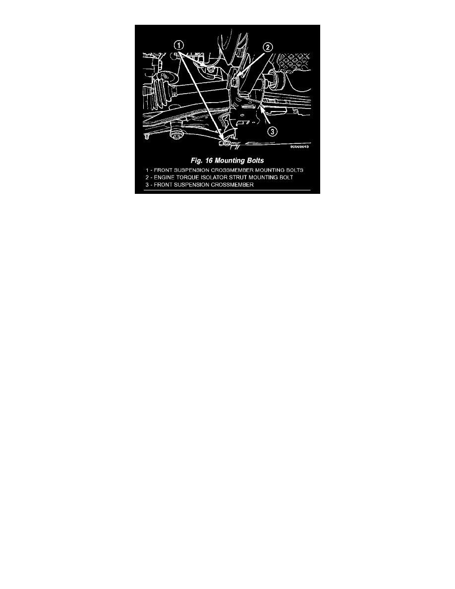
Fig. 16
15. Loosen and completely remove the two front bolts (one right and one left) attaching the front suspension crossmember to the frame rails of
vehicle.The right side bolt can be viewed in the mounting bolt figure (Fig. 16). The left side bolt is located in the same location on the other side of
the vehicle.
16. Loosen the two rear bolts (one right and one left) attaching the front suspension crossmember and lower control arms to the body of the vehicle
until they release from the threaded tapping plates in the body of the vehicle. Remove the rear bolts from the body of the vehicle, but do not
completely remove the rear bolts because they are designed to disengage from the body threads yet stay within the lower control arm rear isolator
bushing. This allows the lower control arm to stay in place on the crossmember. The right side bolt can be viewed in the mounting bolt figure (Fig.
16). The left side bolt is located in the same location on the other side of the vehicle.
17. Lower the front suspension crossmember.
18. Remove each lower control arm from the crossmember by removing the front pivot bolt.
INSTALLATION
1. Install the lower control arms on the front suspension crossmember. Install the pivot bolts, but do not completely tighten them at this time.
2. Using the transmission jack, raise the front suspension crossmember and lower control arms until the crossmember contacts its mounting spot
against the body and frame rails of the vehicle. As the crossmember is raised, carefully guide the power steering gear into mounting position.
3. Start the two rear crossmember mounting bolts into the tapping plates mounted in the body. The right side bolt can be viewed in the mounting bolt
figure (Fig. 16). The left side bolt is located in the same location on the other side of the vehicle. Next, install the two front mounting bolts
attaching front suspension crossmember to frame rails of vehicle. Lightly tighten all four mounting bolts to a approximately 2 N.m (20 in.lbs.) to
hold the front suspension crossmember in position.
NOTE: When reinstalling the front suspension crossmember back in the vehicle, it is very important that the crossmember be attached to the body
in exactly the same spot as when it was removed. Otherwise, the vehicle's wheel alignment settings (caster and camber) will be lost.
4. Using a soft face hammer, tap the front suspension crossmember back-and-forth or side-to-side until it is aligned with the previously scribed
positioning marks on the body of the vehicle (Fig. 15). Once the front suspension crossmember is correctly positioned, tighten the rear two
crossmember mounting bolts to a torque of 203 N.m (150 ft.lbs.), then tighten the front two crossmember mounting bolts to a torque of 142 N.m
(105 ft.lbs.).
5. Tighten the lower control arm front pivot bolts to a torque of 163 N.m (120 ft.lbs.).
6. Attach the steering gear to the front suspension crossmember (Fig. 13). Install the four power steering gear mounting bolts. Tighten the mounting
bolts to a torque of 61 N.m (45 ft.lbs.).
7. Remove the wire or cord suspending the power steering gear to the underbody.
8. Install the two screws securing the cooler to the front suspension crossmember. They are located behind the cooler.
9. Install each ball joint stud into the steering knuckle aligning the bolt hole in the knuckle boss with the notch formed in the side of the ball joint
stud.
10. Install a new ball joint stud pinch bolt and nut (Fig. 11). Tighten the nut to a torque of 95 N.m (70 ft.lbs.).
11. Install the engine torque strut and mounting bolts (Fig. 14). To properly align and tighten the torque strut. Refer to Engine Mount.
12. Install the washer on the end of the stud extending from the torque strut bolt (Fig. 14).
13. Install the pencil strut to the right front corner of the crossmember and body of the vehicle (Fig. 14). Tighten the pencil strut nuts to a torque of 58
N.m (43 ft.lbs.).
14. Install the drive-belt splash shield and fasteners.