
Nitro 2WD V6-4.0L (2007)
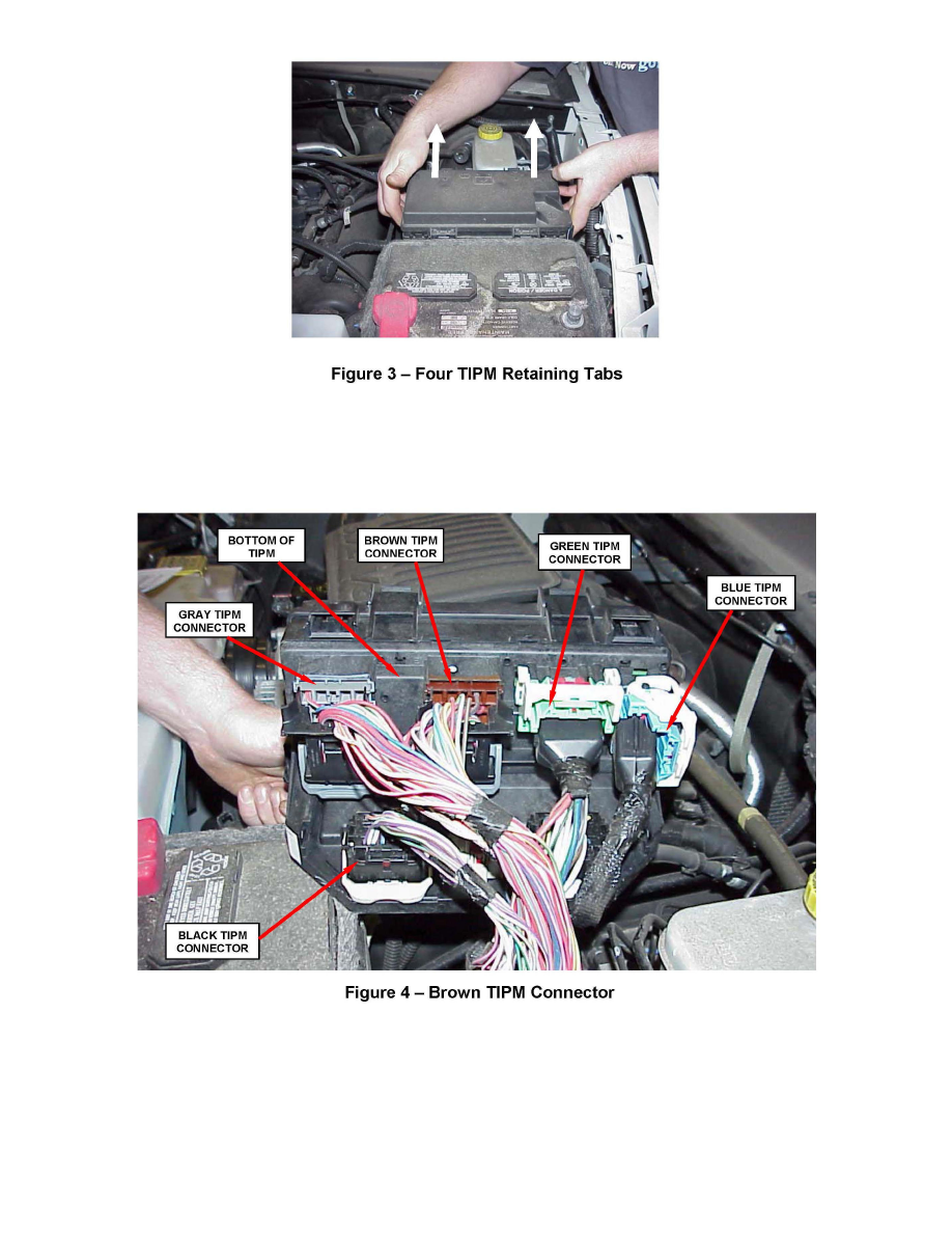
3. Disconnect the TIPM assembly from its mounting bracket by compressing the four retaining tabs and pulling straight upward. This will allow access
to the wiring connectors located on the bottom side of the TIPM (Figure 2 and 3)
4. Connect the brown with white tracer wire and brown with orange tracer wire from the overlay wiring harness to the brown TIPM connector wiring
harness using the following procedure:
a. Disconnect the brown TIPM electrical connector from the
TIPM by first pressing down the center lock tab, and at the same time lifting the gray lock handle and then pulling on the connector body (Figure 4).
b. Remove the electrical tape from the brown connector wiring harness.
c. Remove the black plastic cover from the backside of the brown connector (Figure 5).