
Nitro 2WD V6-4.0L (2007)
NOTE: Extreme pressure lubrication must be used on the threaded portions of the tool. This will increase the longevity of the tool and insure
proper operation during the removal and installation process.
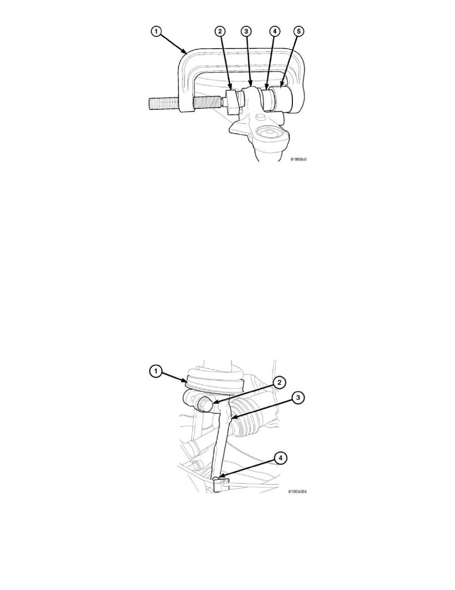
1. Install the new clevis bracket bushing (4) into the lower control arm (3) using special tools C-4212F (Press) (1), 9957-2 (Depth Gauge) (2), 9957-1
(driver) (5).
2. Install the upper ball joint to the knuckle and tighten the nut to 41 Nm (30 ft.lbs.) plus an additional 90° turn.
3. Install the clevis bolt to the lower control arm and tighten the bolt to 150 Nm (110 ft.lbs.).
4. Install the stabilizer link lower bolt to the control arm and tighten the bolt to 102 Nm (75 ft.lbs.).
5. Install the wheel speed sensor.
6. Install the disc brake rotor.
7. Install the tire and wheel assembly.
8. Lower the vehicle.
Removal
REMOVAL
1. Raise and support the vehicle.
2. Remove the tire and wheel assembly.
3. Remove the disc brake rotor.
4. Remove the wheel speed sensor.
5. Remove the lower clevis bolt (4) at the lower control arm.
6. Remove the upper clevis bolt (2) at the shock.
7. Remove the lower stabilizer link bolt at the lower control arm.
8. Remove the upper ball joint nut.
9. Separate the upper ball joint from the knuckle using remover 9360.
10. Swing the knuckle downward to allow clearance to remove the clevis bracket (3).
11. Remove the clevis bracket (3) from the vehicle.