
RAM 1500 Truck 2WD V6-3.7L VIN K (2003)
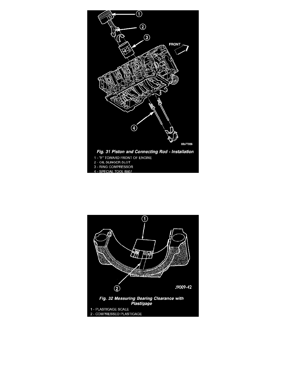
3. Use piston ring compressor and Guide Pins Special Tool 8507 (Fig. 31) to install the rod and piston assemblies. The oil slinger slots in the rods
must face front of the engine. The "F"'s near the piston wrist pin bore should point to the front of the engine.
4. Install the lower bearing insert in the bearing cap. The lower insert must be dry. Place strip of Plastigage across full width of the lower insert at the
center of bearing cap. Plastigage must not crumble in use. If brittle, obtain fresh stock.
5. Install bearing cap and connecting rod on the journal and tighten bolts to 27 Nm (20 ft. lbs.) plus a 90 ° turn. DO NOT rotate crankshaft.
Plastigage will smear, resulting in inaccurate indication.
6. Remove the bearing cap and determine amount of bearing-to-journal clearance by measuring the width of compressed Plastigage (Fig. 32). Refer
to Engine Specifications for the proper clearance. Plastigage should indicate the same clearance across the entire width of the insert. If the
clearance varies, it may be caused by either a tapered journal, bent connecting rod or foreign material trapped between the insert and cap or rod.
7. If the correct clearance is indicated, replacement of the bearing inserts is not necessary. Remove the Plastigage from crankshaft journal and
bearing insert. Proceed with installation.
8. If bearing-to-journal clearance exceeds the specification, determine which services bearing set to use the bearing sizes are as follows: