
RAM 1500 Truck 2WD V6-3.9L VIN X (1999)
Horn Switch: Description and Operation
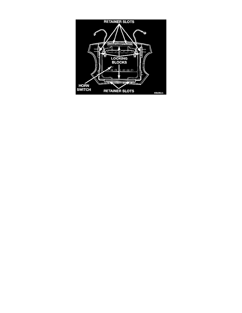
Driver Side Airbag Module Trim Cover And Horn Switch
DESCRIPTION
A center-blow, normally open, resistive membrane-type horn switch is secured with heat stakes to the back side of the driver side airbag module
trim cover in the center of the steering wheel. The switch consists of two plastic membranes, one that is flat and one that is slightly convex. These
two membranes are secured to each other around the perimeter. Inside the switch, the centers of the facing surfaces of these membranes each has a
grid made with an electrically conductive material applied to it. One of the grids is connected to a circuit that provides it with continuity to ground
at all times. The grid of the other membrane is connected to the horn relay control circuit.
The steering wheel and steering column must be properly grounded in order for the horn switch to function properly. The horn switch is only
serviced as a part of the driver side airbag module trim cover. If the horn switch is damaged or faulty, or if the driver side airbag is deployed, the
driver side airbag module trim cover and horn switch must be replaced as a unit.
OPERATION
When the center area of the driver side airbag trim cover is depressed, the electrically conductive grids on the facing surfaces of the horn switch
membranes A contact each other, closing the switch circuit. The completed horn switch circuit provides a ground for the control coil side of the
horn relay, which activates the relay. When the horn switch is released, the resistive tension of the convex membrane separates the two electrically
conductive grids and opens the switch circuit.