
RAM 1500 Truck 2WD V6-3.9L VIN X (1999)
Instrument Cluster Failure Message
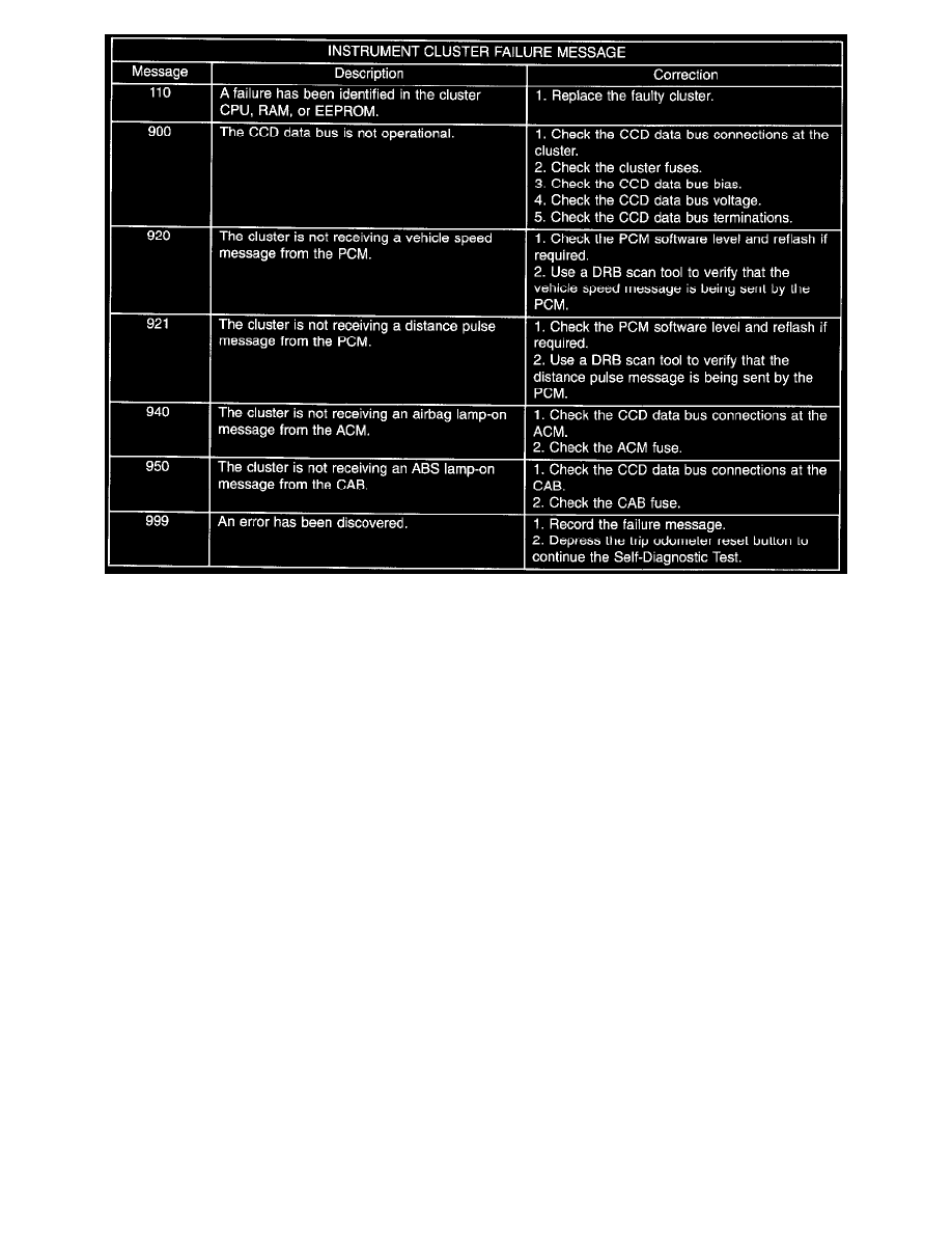
5. A series of three-digit numeric failure messages may appear in the odometer display, depending upon the failure mode. If a failure message
appears, see the Instrument Cluster Failure Message chart for the description and proper correction. If no failure message appears, the
self-diagnostic test will proceed as described in Step 6.
6. The instrument cluster will begin the odometer walking segment test. This test will require the operator to visually inspect each odometer segment
as it is displayed to determine a pass or fail condition. First, all of the segments will be illuminated at once; then, each individual segment of the
odometer display will be illuminated in sequence. If any segment in the display fails to illuminate, repeat the test to confirm the failure. If the
failure is confirmed, replace the faulty instrument cluster. Following the odometer walking segment test, the self-diagnostic test will automatically
proceed as described in Step 7.
7. The instrument cluster will perform a bulb check of each indicator lamp that the instrument cluster circuitry controls. If an individual amber
indicator lamp does not illuminate during this test, the instrument cluster should be removed. However, check that the incandescent lamp bulb is
not faulty and that the bulb holder is properly installed on the instrument cluster electronic circuit board before considering instrument cluster
replacement. If the bulb and bulb holder check OK, replace the faulty instrument cluster. Each of the red indicators are illuminated by a Light
Emitting Diode (LED). If an LED fails to illuminate during this test, the instrument cluster must be replaced. Following the bulb check test, the
self-diagnostic test will automatically proceed as described in Step 8.
8. The instrument cluster will perform a gauge actuator test. In this test the instrument cluster circuitry positions each of the gauge needles at three
different calibration points, then returns the gauge needles to their relaxed positions. If an individual gauge does not respond properly, or does not
respond at all during the gauge actuator test, the instrument cluster should be removed. However, check that the gauge terminal pins are properly
inserted through the spring-clip terminal pin receptacles on the instrument cluster electronic circuit board before considering instrument cluster
replacement. If the gauge terminal connections are OK, replace the faulty instrument cluster.
9. The self-diagnostic test is now completed. The instrument cluster will automatically exit the self-diagnostic mode and return to normal operation at
the completion of the test, if the ignition switch is turned to the Off position during the test, or if a vehicle speed message indicating that the
vehicle is moving is received from the PCM on the CCD data bus during the test.
10. Go back to Step 1 to repeat the test, if required.