
RAM 1500 Truck 2WD V8-5.7L VIN 2 (2006)
Shift Solenoid: Description and Operation
45RFE/545RFE Automatic Transmission
Valve-Solenoid Switch
VALVE-SOLENOID SWITCH
DESCRIPTION
The Solenoid Switch Valve (SSV) is located in the valve body and controls the direction of the transmission fluid when the L/R-TCC solenoid is
energized.
OPERATION
The Solenoid Switch Valve controls line pressure from the L/R-TCC solenoid. In 1st gear, the SSV will be in the downshifted position, thus directing
fluid to the L/R clutch circuit. In 2nd, 3rd, 4th, and 5th (if applicable) gears, the solenoid switch valve will be in the upshifted position and directs the
fluid into the torque converter clutch (TCC) circuit.
When shifting into 1st gear, a special hydraulic sequence is performed to ensure SSV movement into the downshifted position. The L/R pressure
switch is monitored to confirm SSV movement. If the movement is not confirmed (the L/R pressure switch does not close), 2nd gear is substituted for
1st. A DTC will be set after three unsuccessful attempts are made to get into 1st gear in one given key start.
Assembly-Transmission Solenoid/TRS
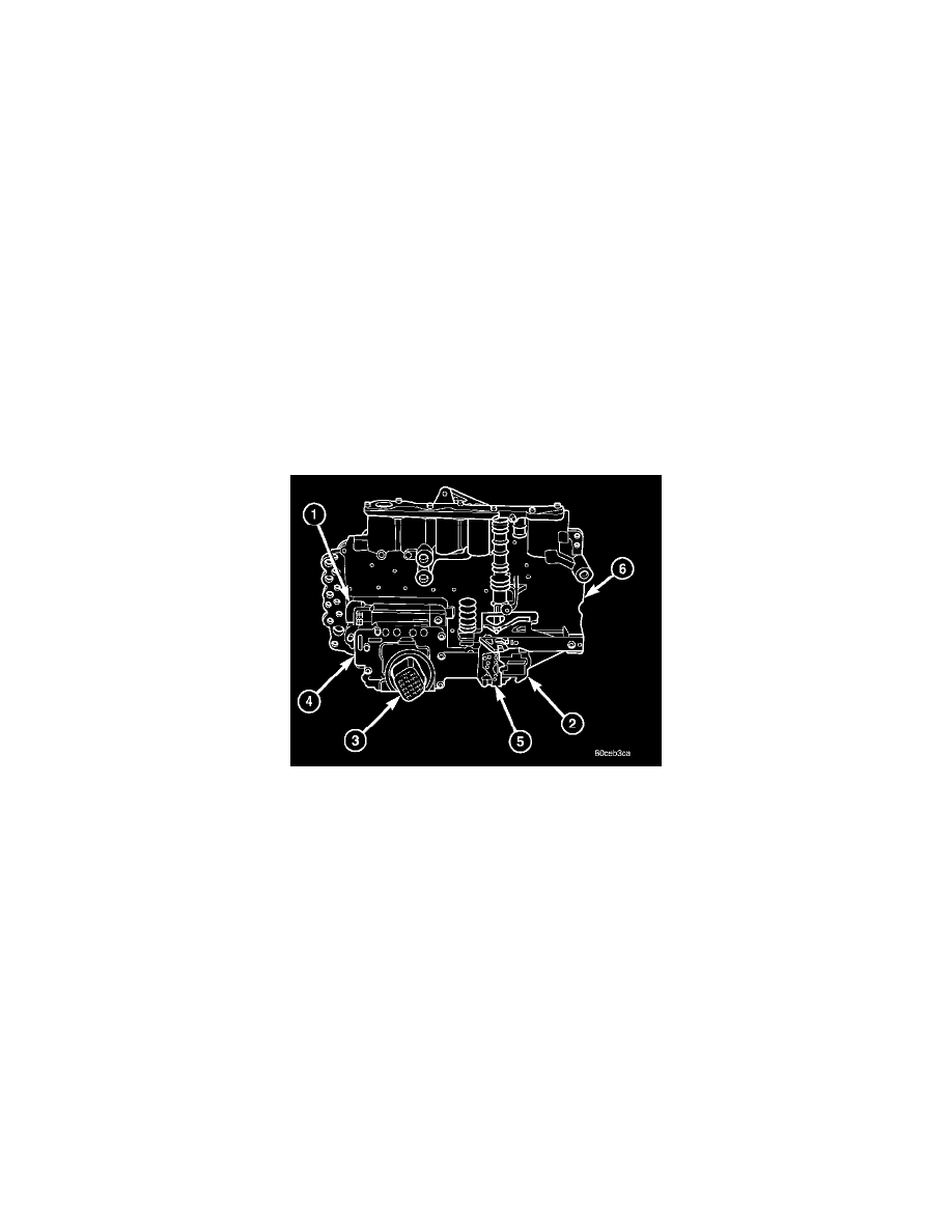
ASSEMBLY-TRANSMISSION SOLENOID/TRS
DESCRIPTION
The transmission solenoid/TRS assembly is internal to the transmission and mounted on the valve body assembly. The assembly consists of six
solenoids that control hydraulic pressure to the six friction elements (transmission clutches), and the torque converter clutch. The pressure control
solenoid is located on the side of the solenoid/TRS assembly. The solenoid/TRS assembly also contains five pressure switches that feed information to
the TCM.
OPERATION
SOLENOIDS
Solenoids are used to control the L/R, 2C, 4C, OD, and UD friction elements. The reverse clutch is controlled by line pressure and the position of the
manual valve in the valve body. All the solenoids are contained within the Solenoid and Pressure Switch Assembly. The solenoid and pressure switch
assembly contains one additional solenoid, MultiSelect (MS), which serves primarily to provide 2nd and 3rd gear limp-in operation.
The solenoids receive electrical power from the Transmission Control Relay through a single wire. The TCM energizes or operates the solenoids
individually by grounding the return wire of the solenoid as necessary. When a solenoid is energized, the solenoid valve shifts, and a fluid passage is
opened or closed (vented or applied), depending on its default operating state. The result is an apply or release of a frictional element.
The MS and UD solenoids are normally applied to allow transmission limp-in in the event of an electrical failure.
The continuity of the solenoids and circuits are periodically tested. Each solenoid is turned on or off depending on its current state. An inductive spike
should be detected by the TCM during this test. If no spike is detected, the circuit is tested again to verify the failure. In addition to the periodic
testing, the solenoid circuits are tested if a speed ratio or pressure switch error occurs.
PRESSURE SWITCHES
The TCM relies on five pressure switches to monitor fluid pressure in the L/R, 2C, 4C, UD and OD hydraulic circuits. The primary purpose of these