RAM 1500 Truck 2WD V8-5.7L VIN D (2003)

-
In-line connectors located in the engine compartment are C100 series numbers
-
In-line connectors located in the Instrument Panel area are C200 series numbers.
-
In-line connectors located in the body are C300 series numbers.
-
Jumper harness connectors are C400 series numbers.
-
Grounds and ground connectors are identified with a "G" and follow the same series numbering as the in-line connectors.
-
Splices are identified with an "S" and follow the same series numbering as the in-line connectors.
-
Component connectors are identified by the component name instead of a number. Multiple connectors on a component use a C1, C2, etc.
identifier.
Locations
Vehicle/Locations contains the master connector/ground/splice location index charts with hyperlinks to the applicable location illustrations. The
illustrations contain the connector name (or number)/ground number/splice number and component identification.
The abbreviation T/O is used in the location column to indicate a point in which the wiring harness branches out to a component. The abbreviation
N/S means Not Shown in the illustrations.
PLEASE NOTE: The master location index charts contain numerous items that may not be applicable to all vehicle models. If a link on the master
location index chart to a figure is not functional, that means that the chart item and/or figure in question does NOT apply to the vehicle model selected.
Connector, Ground and Splice Information
CAUTION: Not all connectors are serviced. Some connectors are serviced only with a harness. A typical example might be the Supplemental Restraint
System connectors. Always check parts availability before attempting a repair.
IDENTIFICATION
Connectors, grounds, and splices are identified as follows:
-
In-line connectors located in the engine compartment are C100 series numbers
-
In-line connectors located in the Instrument Panel area are C200 series numbers.
-
In-line connectors located in the body are C300 series numbers.
-
Jumper harness connectors are C400 series numbers.
-
Grounds and ground connectors are identified with a "G" and follow the same series numbering as the in-line connectors.
-
Splices are identified with an "S" and follow the same series numbering as the in-line connectors.
-
Component connectors are identified by the component name instead of a number. Multiple connectors on a component use a C1, C2, etc.
identifier.
Electrostatic Discharge (ESD) Sensitive Devices
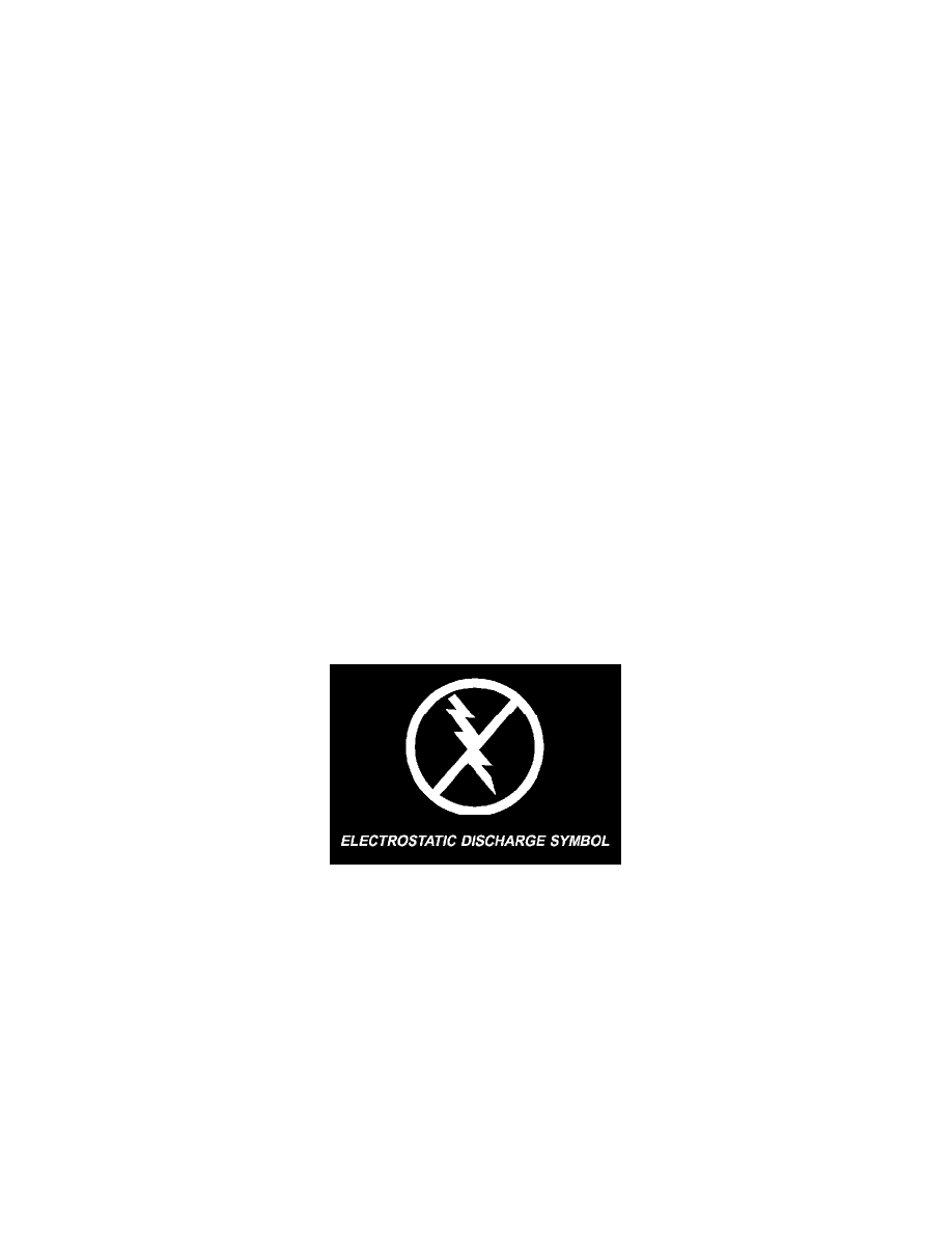
Electrostatic Discharge Symbol
All ESD sensitive components are solid state and a symbol is used to indicate this. When handling any component with this symbol comply with the
following procedures to reduce the possibility of electrostatic charge build up on the body and inadvertent discharge into the component. If it is not
known whether the part is ESD sensitive, assume that it is.
1. Always touch a known good ground before handling the part. This should be repeated while handling the part and more frequently after sliding
across a seat, sitting down from a standing position, or walking a distance.
2. Avoid touching electrical terminals of the part, unless instructed to do so by a written procedure.
3. When using a voltmeter, be sure to connect the ground lead first.
4. Do not remove the part from its protective packing until it is time to install the part.
5. Before removing the part from its package, ground the package to a known good ground on the vehicle.
Notes, Cautions and Warnings
Additional important information is presented in three ways: Notes, Cautions, and Warnings.
NOTES are used to help describe how switches or components operate to complete a particular circuit. They are also used to indicate different
