
RAM 1500 Truck 4WD V8-4.7L (2008)
Four Wheel Drive Selector Switch: Description and Operation
NV244 GENII Transfer Case
Description
DESCRIPTION
The selector switch assembly is mounted in the left side of the vehicle's Instrument Panel (IP) and consists of a rotary knob connected to a resistive
network for the mode and range shift selections. Also located in this assembly is a recessed, normally open momentary switch for making shifts into and
out of transfer case NEUTRAL. A pen, or similar instrument, is used to make a NEUTRAL shift selection, thus reducing the likelihood of an inadvertent
shift request.
The selector switch also contains light emitting diode's (LED's) to indicate the transfer case position and whether a shift is in progress.
Operation
OPERATION
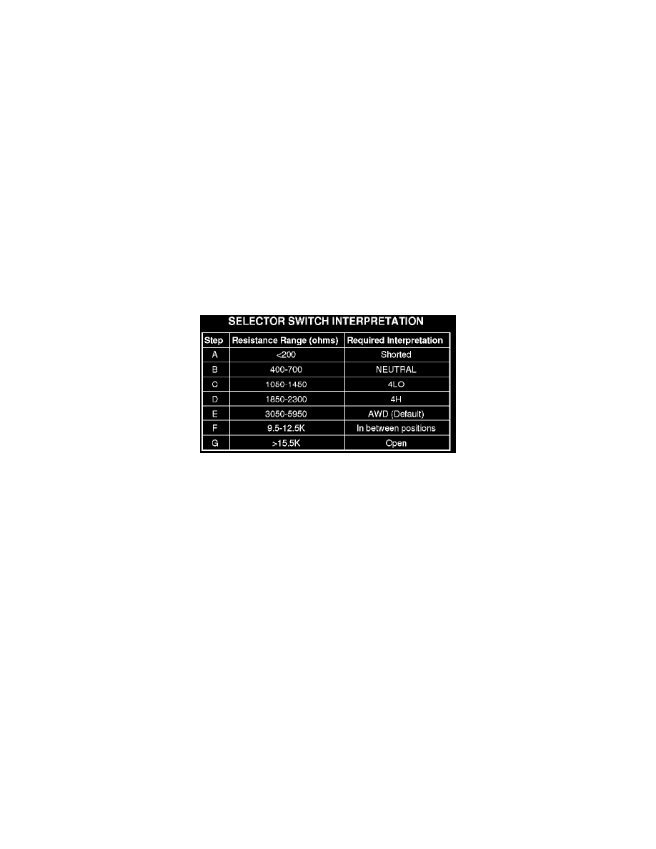
As the position of the selector switch varies, the resistance between the Mode Sensor supply voltage pin and the Mode Sensor output will vary.
Hardware, software, and calibrations within the Transfer Case Control Module (TCCM) are provided that interpret the selector switch resistance as given
in the table below:
For resistances between the ranges B-E shown for each valid position (T-Case NEUTRAL, 4LO, 4HI, AWD), the TCCM may interpret the resistance as:
-
either of the neighboring valid positions.
-
as an invalid fault position.
For resistances between the ranges E and F shown for AWD and in-between positions, the TCCM may interpret the resistance as:
-
the AWD position.
-
an invalid fault position.
-
a valid in-between position.
For resistances between the ranges F and G shown for in-between positions and fault condition (open), the TCCM may interpret the resistance as:
-
a valid in-between position.
-
an invalid fault position.
For resistances between the ranges A and B shown for the fault condition (short) and , T-Case NEUTRAL, the TCCM may interpret the resistance as:
-
the T-Case NEUTRAL position.
-
an invalid fault position.
The LED's in the selector assembly are illuminated/flashed in the following manner to indicate a particular condition or state.
-
A solidly illuminated LED indicates a successfully completed shift and the current operating mode of the transfer case. While a shift has been
requested but not yet completed, the LED for the desired transfer case position is flashed.
-
A flashing operating mode LED for the desired gear indicates that a shift to that position has been requested, but all of the driver controllable
conditions have not been met. This is in an attempt to notify the driver that the transmission needs to be put into NEUTRAL, the vehicle speed is
too great, or some other condition outlined (other than a diagnostic failure that would prevent this shift) elsewhere See: Relays and Modules -
Transmission and Drivetrain/Relays and Modules - Transfer Case/Control Module/Description and Operation/Operation is not met. Note that this