
RAM 1500 Truck 4WD V8-4.7L (2008)
1. While holding the centered clockspring rotor and case stationary in relation to each other, or with the plastic locking pin (1) installed, carefully
slide the clockspring down over the steering column (3) upper shaft.
2. Align and seat the hole in the locating tab on the clockspring case over the locating pin on the multi-function switch mounting housing.
3. Install and tighten the two screws (2) that secure the clockspring to the multi-function switch mounting housing. Tighten the screws to 2 Nm (20
in. lbs.).
4. Reconnect the two instrument panel wire harness connectors to the two connector receptacles located below the steering column on the back of the
clockspring housing.
5. On vehicles equipped with the Electronic Stability Program (ESP), reconnect the instrument panel wire harness connector to the applied connector
for the Steering Angle Sensor (SAS) located below the steering column on the back of the clockspring housing.
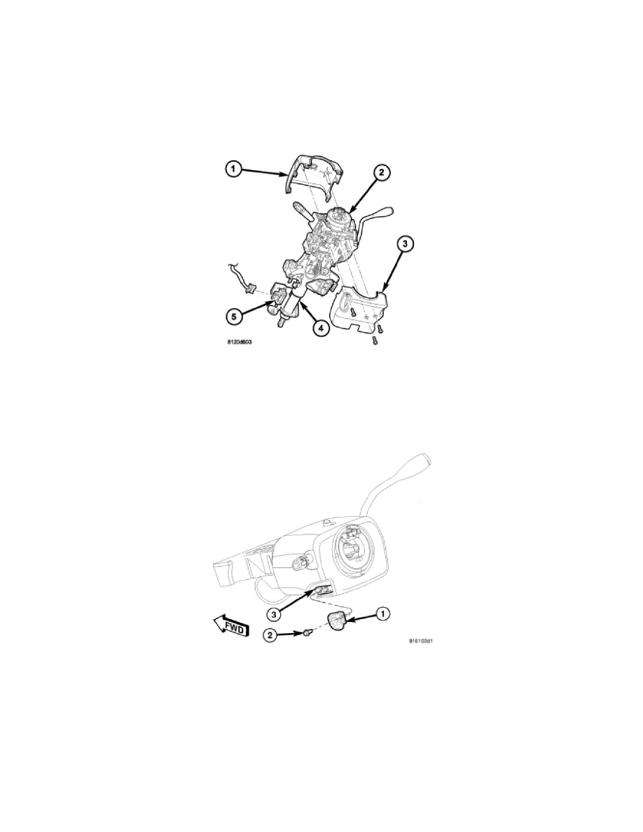
6. Position the lower shroud (3) onto the steering column (4).
7. From below the steering column, install and tighten the one center screw that secures the lower shroud to the steering column. Tighten the screw to
2 Nm (20 in. lbs.).
8. Position the upper shroud (1) onto the steering column over the lower shroud. If the vehicle is equipped with an automatic transmission, be certain
to engage the gearshift lever gap hider into the opening in the right side of both shroud halves.
9. Align the snap features on the upper shroud with the receptacles on the lower shroud and apply hand pressure to snap them together.
10. Install and tighten the two outboard screws that secure the upper shroud to the lower shroud. Tighten the screws to 2 Nm (20 in. lbs.).
11. Position the tilt steering column knob (1) onto the tilt adjuster actuator (3) on the left side of the steering column, then install and tighten the screw
(2) to secure the knob to the actuator. Tighten the screw to 2 Nm (20 in. lbs.).
12. Reinstall the steering column opening cover onto the instrument panel. See: Body and Frame/Interior Moulding / Trim/Dashboard / Instrument
Panel/Service and Repair/Steering Column Opening Cover - Installation .
13. If a new clockspring has been installed, remove the plastic locking pin that is securing the clockspring rotor to the clockspring case to maintain
clockspring centering.
NOTE: When reinstalling the steering wheel, be certain to index the engagement dowel on the upper surface of the clockspring rotor
between the two fins cast into the lower surface of the steering wheel armature hub.
14. Reinstall the steering wheel onto the steering column. See: Steering and Suspension/Steering/Steering Wheel/Service and Repair/Installation .
15. Reconnect the steering wheel wire harness connectors to the upper clockspring connector receptacles. Be certain that the steering wheel wire