
RAM 1500 Truck 4WD V8-4.7L VIN N (2003)
Winch Relay: Description and Operation
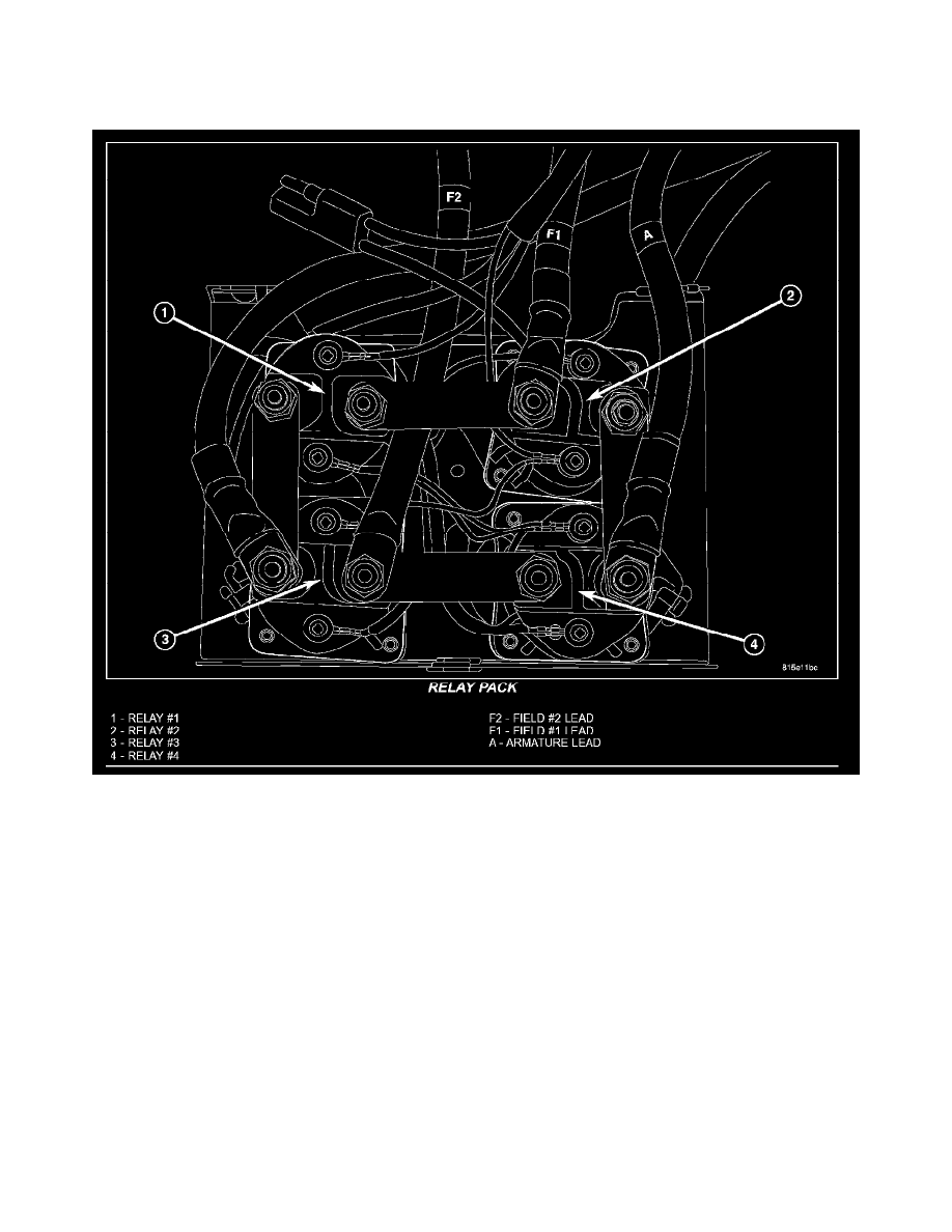
RELAY PACK
DESCRIPTION
Relay Pack
Electrical operation of the control assembly consists of four heavy duty relays, a thermal-switch located on the motor armature brush holder and a Low
Voltage Interrupt (LVI) located in the control assembly. The thermal-switch interrupts the power-in function and the LVI affects both the power-in and
power-out functions and must be reset by allowing the charging circuit voltage to rise above 10 volts for more than 30 seconds. The thermal switch is
reset only by allowing the winch motor to cool adequately (about 30 minutes). Relay number 1 and 3 control current flow through the field windings
and relay number 2 and 4 supply current to the motor armature.
OPERATION
In the power-out mode, relay number 2 and 3 are energized by the remote control switch. Current flows from the positive battery terminal through relay
number 3 then through the black motor cable to the number 2 and number 1 field windings. From the black motor cable current then flows through
solenoid number 2 to the motor armature to ground.
In power-in mode, relay number 1 and 4 are energized. Current again flows from the battery positive cable, but this time current flows through solenoid
number 1 then through field winding number 1. Current flowing in the reverse direction through the field windings cause the motor to turn in the
opposite direction. From the red motor cable current then flows through relay number 4 to the black cable going to the motor armature to ground.