
RAM 1500 Truck 4WD V8-5.7L VIN D (2005)
Compass: Description and Operation
MODULE-COMPASS TEMPERATURE
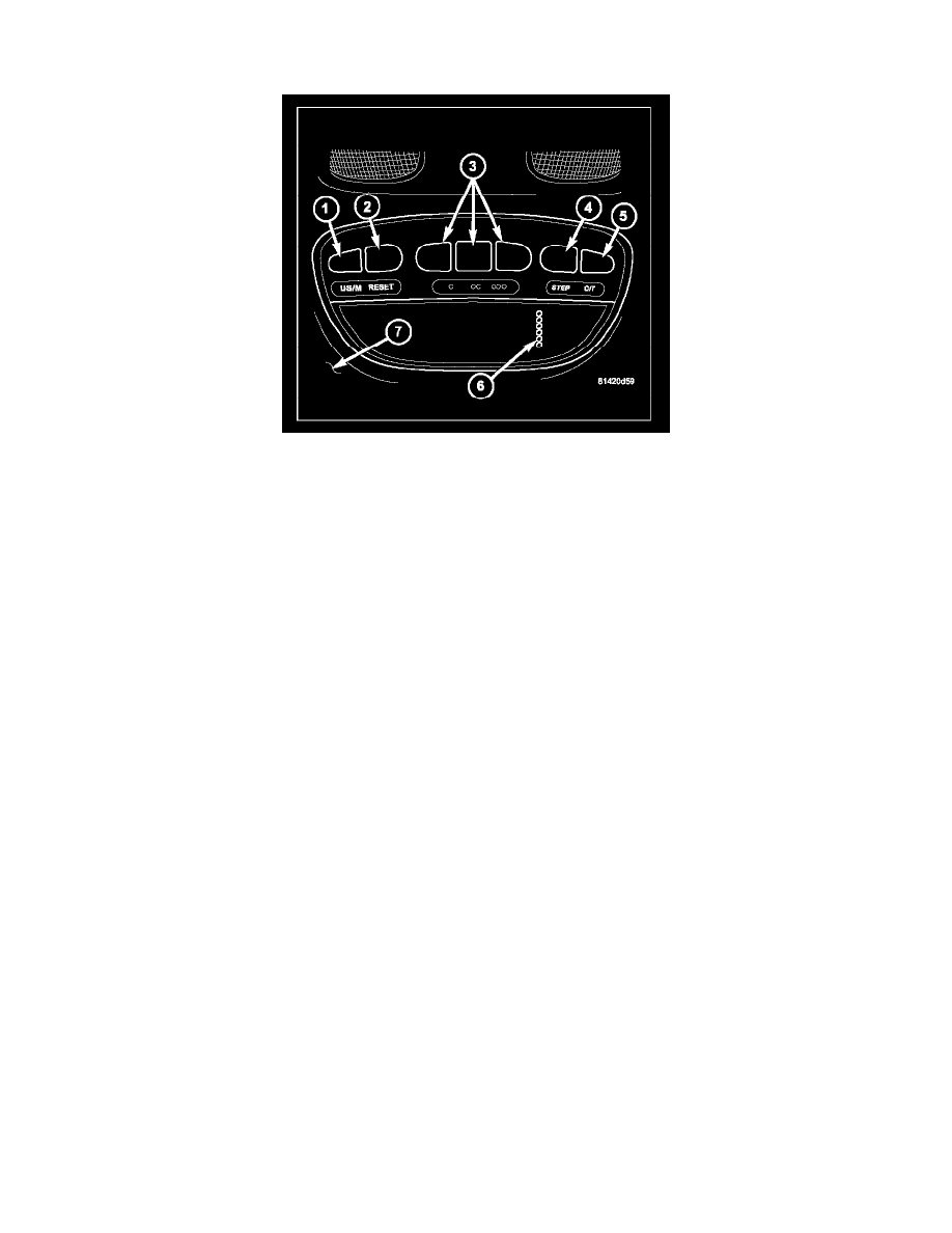
The compass mini-trip computer is located in the overhead console (7) on models equipped with this option. The compass mini-trip computer includes a
Vacuum-Fluorescent Display (VFD) (6), an Electronic Overhead Module (EOM) and push button function switches (1, 2, 4 and 5).
The compass mini-trip computer module contains a central processing unit and interfaces with other electronic modules in the vehicle on the
Programmable Communications Interface (PCI) data bus. The PCI data bus allows the sharing of sensor information. This helps to reduce wire harness
complexity, reduce internal controller hardware, and reduce component sensor current loads. At the same time, this system provides increased reliability,
enhanced diagnostics, and allows the addition of many new feature capabilities.
The compass mini-trip computer provides several electronic functions and features. Some of the functions and features that the compass mini-trip
computer supports and/or controls, include the following display options:
-
Compass and temperature - provides the outside temperature and one of eight compass readings to indicate the direction the vehicle is facing.
-
Trip odometer (TRIP ODO) - shows the distance travelled since the last trip computer reset.
-
Average fuel economy (AVG ECO) - shows the average fuel economy since the last trip computer reset.
-
Distance to empty (DTE) - shows the estimated distance that can be travelled with the fuel remaining in the fuel tank. This estimated distance is
computed using the level of the fuel in the tank and a weighted average of long term and recent Average Fuel Economy.
-
Elapsed time (ET) - shows the accumulated ignition-on time since the last trip computer reset.
-
Blank screen - the compass mini-trip VFD is turned off.
The ambient temperature sensor is hard wired to the Front Control Module (FCM). Data input for all other compass mini-trip computer functions,
including VFD dimming level, is received through PCI data bus messages. The compass mini-trip computer uses its internal programming and all of
these inputs to calculate and display the requested data. If the data displayed is incorrect, perform the self-diagnostic tests. If these tests prove
inconclusive, the use of a scan tool and the proper Diagnostic Procedures Information are recommended for further testing of the EOM and the PCI data
bus.
The EOM cannot be repaired, and is available for service only as a unit. This unit includes the push button switches, the Universal Garage Door
Transmitter and the plastic module and display lens. If any of these components is inoperative or damaged, the complete EOM must be replaced.
COMPASS
While in the compass/temperature mode, the compass will display the direction in which the vehicle is pointed using the eight major compass headings
(Examples: north is N, northeast is NE). The self-calibrating compass unit requires no adjusting in normal use. The only calibration that may prove
necessary is to drive the vehicle in one or two complete circles, on level ground, in not less than 16 seconds. This will reorient the compass unit to its
vehicle.
The compass unit also will compensate for magnetism the body of the vehicle may acquire during normal use. However, avoid placing anything magnetic
directly on the roof of the vehicle. Magnetic mounts for an antenna, a repair order hat, or a funeral procession flag can exceed the compensating ability
of the compass unit if placed on the roof panel. Magnetic bit drivers used on the fasteners that hold the overhead console assembly to the roof header can
also affect compass operation. If the vehicle roof should become magnetized.
TEMPERATURE
The temperature displays the outside ambient temperature in whole degrees. The temperature display can be changed from Fahrenheit to Celsius using