
RAM 1500 Truck 4WD V8-5.7L VIN D (2005)
Headlamp Switch: Description and Operation
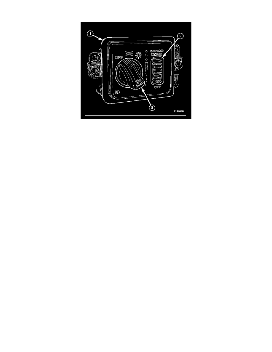
The headlamp switch (1) is located on the instrument panel, to the left of the steering column. Two different switches are used. The standard switch
features a three-position rotary knob (3) for exterior lighting control and a thumbwheel (2) for panel lamps dimming and interior lighting control. An
optional switch has the same thumbwheel, but has an additional "Pull" function added to the rotary knob for selecting the optional front fog lamps.
Each of these switches is constructed of molded plastic. The rotary knob is molded plastic and has a raised center lever to ease operator control. The
thumbwheel is also plastic and knurled. The optional front fog lamp rotary knob is plastic with a smooth finish and an International Control and Display
Symbol icon for "Front Fog Light" applied to it. The switch face plate is also labeled with graphics and icons to clearly identify the many functions of the
rotary knob and thumbwheel.
Three screws secure the switch to the back of the cluster bezel through integral mounting flanges that are molded to each side of the switch housing. The
back of the switch housing has an integral connector receptacle containing terminal pins that connect the switch to the vehicle electrical system through a
dedicated take out and connector of the instrument panel wire harness. A panel dimmer controlled incandescent bulb soldered to the circuit board within
the switch provides back lighting for visibility at night, but is not serviceable. The headlamp switch cannot be repaired and, if faulty or damaged, it must
be replaced.
The headlamp switch uses two resistor multiplexed outputs to control the many functions and features it provides. The switch receives a clean ground
from the ElectroMechanical Instrument Cluster (EMIC) (also sometimes referred to as the Cab Control Node/CCN) on a headlamp switch return circuit.
It then provides outputs to the EMIC on a headlamp switch signal circuit to control exterior lighting functions, and on a panel lamps dimmer signal
circuit to control panel dimmer and interior lighting functions.
The switch illumination circuit receives a path to ground at all times through the left instrument panel ground circuit. The illumination level is controlled
by a Pulse-Width Modulated (PWM) output received from the EMIC on a headlamp switch illumination control circuit. The EMIC controls this output
based upon the dimmer signal select mux input from the headlamp switch.
-
Front Fog Lamps Control - For vehicles so equipped, the rotary knob on the headlamp switch is pulled out to activate or pushed in to deactivate
the optional front fog lamps. The headlamp switch provides an output to the EMIC, and the EMIC responds by sending electronic fog lamp switch
status messages to the Front Control Module (FCM) over the Programmable Communications Interface (PCI) data bus. The FCM responds by
energizing or de-energizing the front fog lamp relay in the Power Distribution Center (PDC).
-
Exterior Lighting Control - The rotary knob on the headlamp switch is rotated to a detent position to activate or deactivate the exterior lighting.
The headlamp switch provides an output to the EMIC, and the EMIC responds by sending electronic exterior lighting switch status messages to the
FCM over the PCI data bus. The FCM responds by energizing or de-energizing the park lamp relay in the PDC and the high or low beam
headlamp circuits. The FCM remembers which headlamp beams were last selected using the multi-function switch, and energizes those beams by
default the next time the headlamps are turned On.
-
Interior Lighting Control - The thumbwheel on the headlamp switch is rotated to the dome defeat, dome on, parade/funeral mode, or one of the
six panel dimmer detent positions to control the interior courtesy/dome and panel lamps. The headlamp switch provides an output to the EMIC,
and the EMIC responds by providing the appropriate interior lighting control outputs through its internal courtesy lamp driver circuits, electronic
dimming level messages to other modules over the PCI data bus, and/or the proper PWM outputs to control dimming levels through several panel
dimmer illumination control driver circuits.
The headlamp switch can be diagnosed using conventional diagnostic tools and methods. However, proper testing of the multiplexed inputs to and PWM
processing of the EMIC requires the use of a diagnostic scan tool.