
RAM 1500 Truck 4WD V8-5.7L VIN D (2005)
Air Bag Control Module: Description and Operation
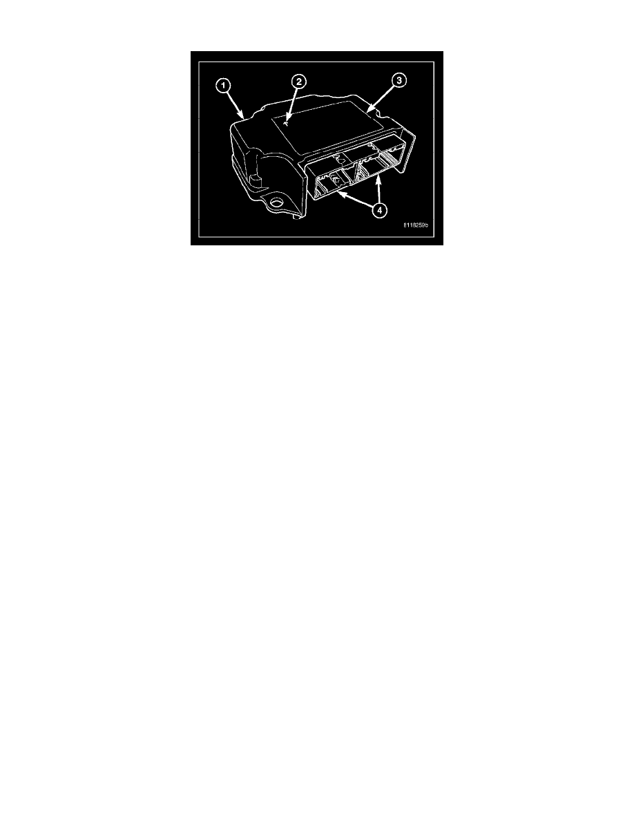
The Airbag Control Module (ACM) (1) is also sometimes referred to as the Occupant Restraint Controller (ORC). The ACM is located below the
instrument panel center stack in the passenger compartment of the vehicle, where it is secured by three screws to a stamped steel mounting bracket
welded onto the top of the floor panel transmission tunnel just forward of the instrument panel center support bracket. Concealed within a hollow in the
center of the die cast aluminum ACM housing is the electronic circuitry of the ACM which includes a microprocessor, an electronic impact sensor, an
electronic sating sensor, and an energy storage capacitor. A stamped metal cover plate is secured to the bottom of the ACM housing with four screws to
enclose and protect the internal electronic circuitry and components.
An arrow (2) printed on the label (3) on the top of the ACM housing provides a visual verification of the proper orientation of the unit, and should
always be pointed toward the front of the vehicle. The ACM housing has integral mounting flanges on three corners. The mounting flange to the left of
the connector receptacle has an integral locating pin on its lower surface. Both left side flanges have round mounting holes, while the flange on the right
side has a slotted mounting hole. A molded plastic electrical connector (4) with two receptacles, one containing twenty-four terminal pins and the other
containing thirty-two terminal pins, exits the rearward facing side of the ACM housing. These terminal pins connect the ACM to the vehicle electrical
system through two dedicated take outs and connectors of the instrument panel wire harness.
The impact sensor and sating sensor internal to the ACM are calibrated for the specific vehicle, and are only serviced as a unit with the ACM. In
addition, there are unique versions of the ACM for light and heavy-duty models, and for vehicles with or without the optional side curtain airbags. The
ACM cannot be repaired or adjusted and, if damaged or faulty, it must be replaced.
The microprocessor in the Airbag Control Module (ACM) contains the supplemental restraint system logic circuits and controls all of the supplemental
restraint system components. The ACM uses On-Board Diagnostics (OBD) and can communicate with other electronic modules in the vehicle as well as
with the diagnostic scan tool using the Programmable Communications Interface (PCI) data bus network. This method of communication is used for
control of the airbag indicator in the ElectroMechanical Instrument Cluster (EMIC) and for supplemental restraint system diagnosis and testing through
the 16-way data link connector located on the driver side lower edge of the instrument panel.
The ACM microprocessor continuously monitors all of the supplemental restraint system electrical circuits to determine the system readiness. If the
ACM detects a monitored system fault, it sets an active and stored Diagnostic Trouble Code (DTC) and sends electronic messages to the EMIC over the
PCI data bus to turn on the airbag indicator. An active fault only remains for the duration of the fault, or in some cases for the duration of the current
ignition switch cycle, while a stored fault causes a DTC to be stored in memory by the ACM. For some DTCs, if a fault does not recur for a number of
ignition cycles, the ACM will automatically erase the stored DTC. For other internal faults, the stored DTC is latched forever.
In standard cab models, the ACM also monitors a resistor multiplexed input from the passenger airbag on/off switch and provides a control output for the
Off indicator in the switch through a passenger airbag indicator driver circuit. If the passenger airbag on/off switch is set to the Off position, the ACM
turns on the passenger airbag on/off switch Off indicator and will internally disable the passenger airbag from being deployed. The ACM also turns on
the on/off switch Off indicator for about seven seconds each time the ignition switch is turned to the On position as a bulb test. Following the bulb test,
the ACM controls the status of the Off indicator based upon the resistance of the input from the on/off switch. The ACM will also set and/or store a DTC
for faults it detects in the passenger airbag on/off switch circuits, and will turn on the airbag indicator in the EMIC if a fault has been detected.
The ACM receives battery current through two circuits; a fused ignition switch output (run) circuit through a fuse in the Integrated Power Module (IPM),
and a fused ignition switch output (run-start) circuit through a second fuse in the IPM. The ACM receives ground through a ground circuit and take out
of the instrument panel wire harness. This take out has a single eyelet terminal connector that is secured by a ground screw to the instrument panel
structural support. These connections allow the ACM to be operational whenever the ignition switch is in the Start or On positions.
The ACM also contains an energy-storage capacitor. When the ignition switch is in the Start or On positions, this capacitor is continually being charged
with enough electrical energy to deploy the supplemental restraint components for up to one second following a battery disconnect or failure. The
purpose of the capacitor is to provide backup supplemental restraint system protection in case there is a loss of battery current supply to the ACM during
an impact.