
RAM 1500 Truck 4WD V8-5.7L VIN D (2005)
Air Bag Control Module: Service and Repair
Module
WARNING:
-
TO AVOID PERSONAL INJURY OR DEATH, ON VEHICLES EQUIPPED WITH AIRBAGS, DISABLE THE SUPPLEMENTAL
RESTRAINT SYSTEM BEFORE ATTEMPTING ANY STEERING WHEEL, STEERING COLUMN, AIRBAG, SEAT BELT
TENSIONER, IMPACT SENSOR, OR INSTRUMENT PANEL COMPONENT DIAGNOSIS OR SERVICE. DISCONNECT AND
ISOLATE THE BATTERY NEGATIVE (GROUND) CABLE, THEN WAIT TWO MINUTES FOR THE SYSTEM CAPACITOR TO
DISCHARGE BEFORE PERFORMING FURTHER DIAGNOSIS OR SERVICE. THIS IS THE ONLY SURE WAY TO DISABLE
THE SUPPLEMENTAL RESTRAINT SYSTEM. FAILURE TO TAKE THE PROPER PRECAUTIONS COULD RESULT IN
ACCIDENTAL AIRBAG DEPLOYMENT.
-
TO AVOID PERSONAL INJURY OR DEATH, NEVER STRIKE OR DROP THE AIRBAG CONTROL MODULE, AS IT CAN
DAMAGE THE IMPACT SENSOR OR AFFECT ITS CALIBRATION. THE AIRBAG CONTROL MODULE CONTAINS THE
IMPACT SENSOR, WHICH ENABLES THE SYSTEM TO DEPLOY THE SUPPLEMENTAL RESTRAINTS. IF AN AIRBAG
CONTROL MODULE IS ACCIDENTALLY DROPPED DURING SERVICE, THE MODULE MUST BE SCRAPPED AND
REPLACED WITH A NEW UNIT. FAILURE TO OBSERVE THIS WARNING COULD RESULT IN ACCIDENTAL, INCOMPLETE,
OR IMPROPER SUPPLEMENTAL RESTRAINT DEPLOYMENT.
REMOVAL
1. Disconnect and isolate the battery negative cable. Wait two minutes for the system capacitor to discharge before further service.
2. On models with a manual transmission, remove the floor console from the top of the floor panel transmission tunnel.
3. On models with an automatic transmission, remove the ACM cover from the instrument panel.
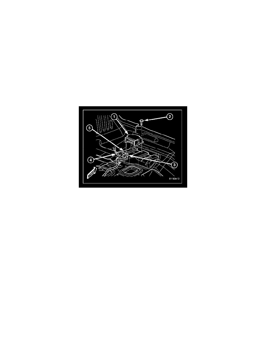
4. Reach through the rearward facing opening below the instrument panel center stack support bracket on the top of the floor panel transmission
tunnel to access and disconnect the two wire harness connectors (3 & 4) for the Airbag Control Module (ACM) (1) from the ACM connector
receptacles located on the rearward facing side of the module. To disconnect the wire harness connectors from the ACM, depress the release tab
and lift the lever arm on each connector.
5. From the left side of the floor panel transmission tunnel, reach behind the module to access and loosen the screw (2) that secures the right side of
the ACM to the bracket (5) on the floor panel transmission tunnel. Loosen the screw about 7 millimeters (0.25 inch).
6. From the left side of the floor panel transmission tunnel, remove the two screws that secure the left side of the ACM to the bracket on the floor
panel transmission tunnel.
7. Still working from the left side of the floor panel transmission tunnel, lift the ACM upward far enough to disengage the locating pin on the bottom
of the ACM mounting flange from the locating hole in the mounting bracket, then slide the ACM toward the left far enough to disengage the
slotted hole in the right ACM mounting flange from under the head of the previously loosened right mounting screw.
8. Remove the ACM from the left side of the floor panel transmission tunnel.
INSTALLATION