
RAM 1500 Truck 4WD V8-5.7L VIN D (2005)
Gear Sensor/Switch: Description and Operation
NV244 GenII
Sensor-Mode
SENSOR-MODE
DESCRIPTION
The transfer case mode sensor is an electronic device whose output can be interpreted to indicate the shift motor shaft's rotary position. The sensor
consists of a magnetic ring and four Hall Effect Transistors to create a 4 channel digital device (non-contacting) whose output converts the motor shaft
position into a coded signal. The TCCM must supply 5VDC (+/0.5v) to the sensor and monitor the shift motor position. The four channels are denoted
A, B. C, and D. The sensor is mechanically linked to the shaft of the cam which causes the transfer case shifting. The mode sensor draws less than 53
mA.
OPERATION
During normal vehicle operation, the Transfer Case Control Module (TCCM) monitors the mode sensor outputs at least every 250 (+/-50)
milliseconds when the shift motor is stationary and 400 microseconds when the shift motor is active. A mode sensor signal between 3.8 Volts and 0.8
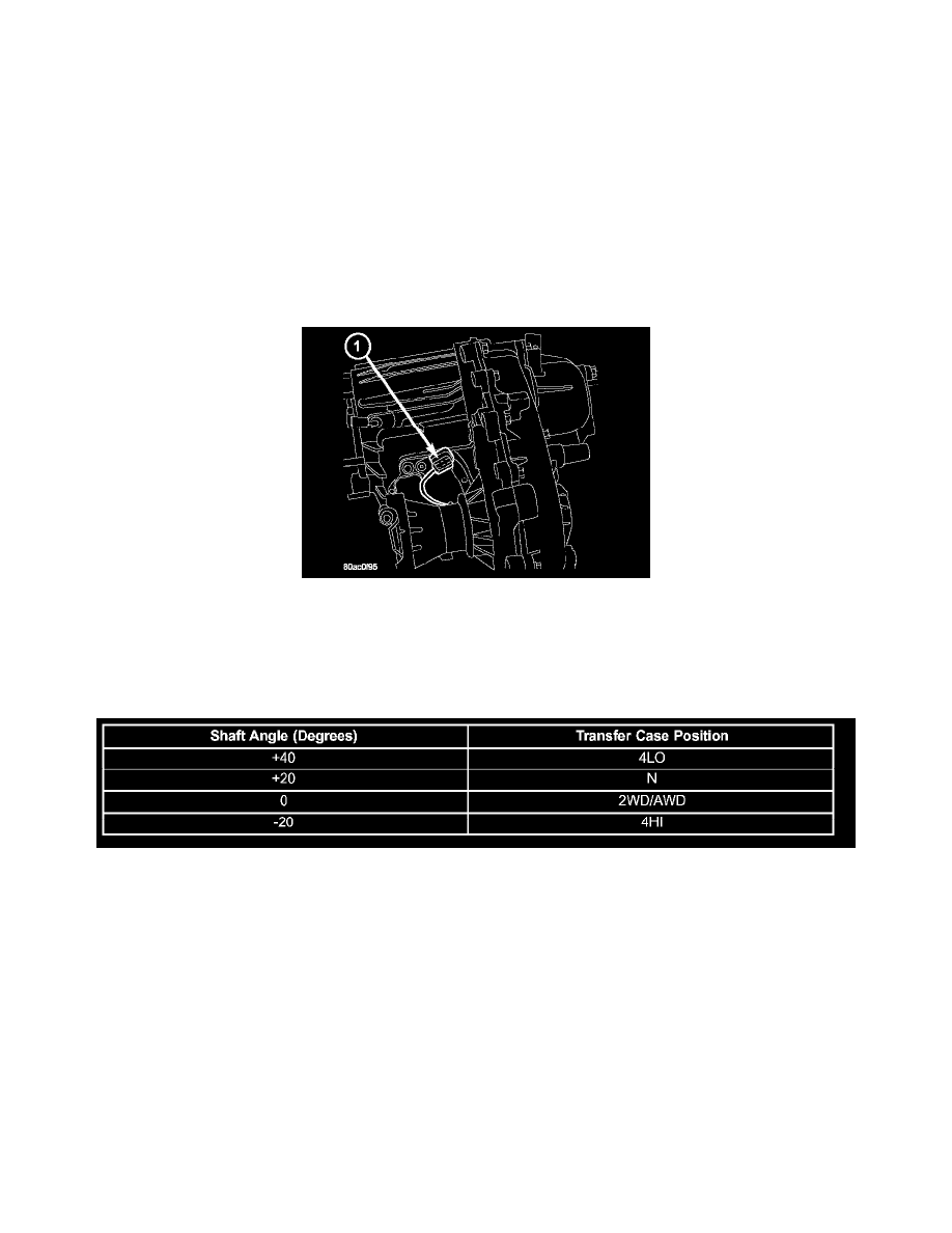
Volts is considered to be undefined. Refer to SECTOR ANGLES vs. TRANSFER CASE POSITION for the relative angles of the transfer case shift
sector versus the interpreted transfer case gear operating mode. Refer to MODE SENSOR CHANNEL STATES for the sensor codes returned to the
TCCM for each transfer case mode sensor position. The various between gears positions can also be referred as the transfer case's coarse position.
These coarse positions come into play during shift attempts.
SECTOR ANGLES vs. TRANSFER CASE POSITION