
RAM 1500 Truck 4WD V8-5.7L VIN D (2005)
Electrical Accessory Panel: Description and Operation
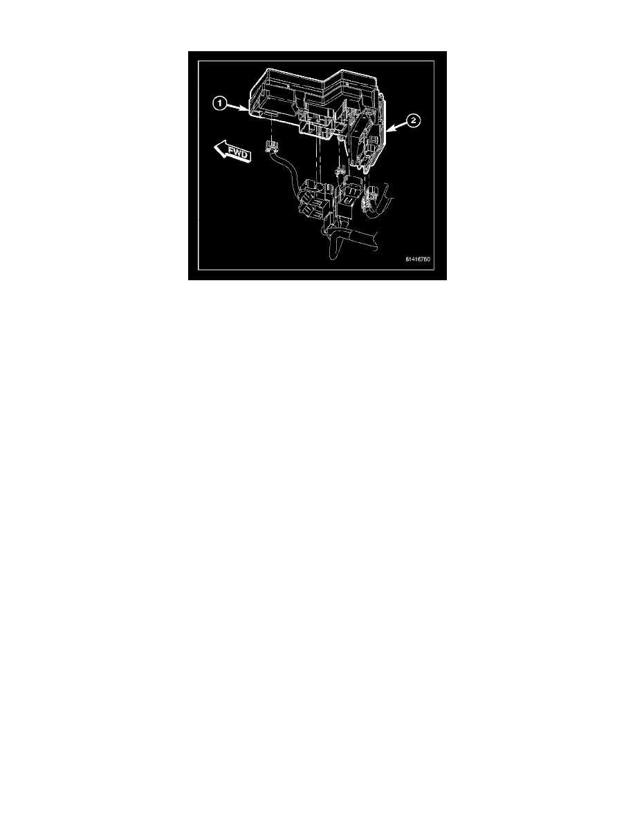
The Integrated Power Module (IPM) is a combination of the Power Distribution Center (PDC) (1) and the Front Control Module (FCM) (2). The PDC
mates directly with the FCM to form the IPM. The PDC is a printed circuit board based module that contains fuses and relays, while the FCM contains
the electronics controlling the IPM and other functions. The IPM is located in the engine compartment, next to the battery and connects directly to the
battery positive via a stud located on top of the unit. The ground connection is via electrical connectors. The IPM provides the primary means of voltage
distribution and protection for the entire vehicle.
The molded plastic IPM housing includes a base and cover. The IPM cover is easily opened or removed for service access by unscrewing the cover
retaining nut and has a fuse and relay layout map integral to the inside surface of the cover. This IPM housing base and cover are secured in place via
bolts to the left front fender support assembly.
Replaceable components of the IPM assembly are broken down into the following components:
-
The Power Distribution Center (PDC)
-
The IPM cover
-
The Front Control Module (FCM)
-
Complete IPM assembly that includes all three parts
All of the current from the battery and the generator output enters the integrated power module via a stud on the top of the module. The integrated power
module cover is removed to access the fuses or relays. Internal connections of all of the power distribution center circuits is accomplished by a
combination of bus bars and a printed circuit board.
For complete circuit diagrams, refer to the appropriate wiring information. The wiring information includes wiring diagrams, proper wire and connector
repair procedures, details of wire harness routing and retention, connector pin-out information and location views for the various wire harness
connectors, splices and grounds.