
RAM 1500 Truck 4WD V8-5.7L VIN D (2005)
Control Module: Description and Operation
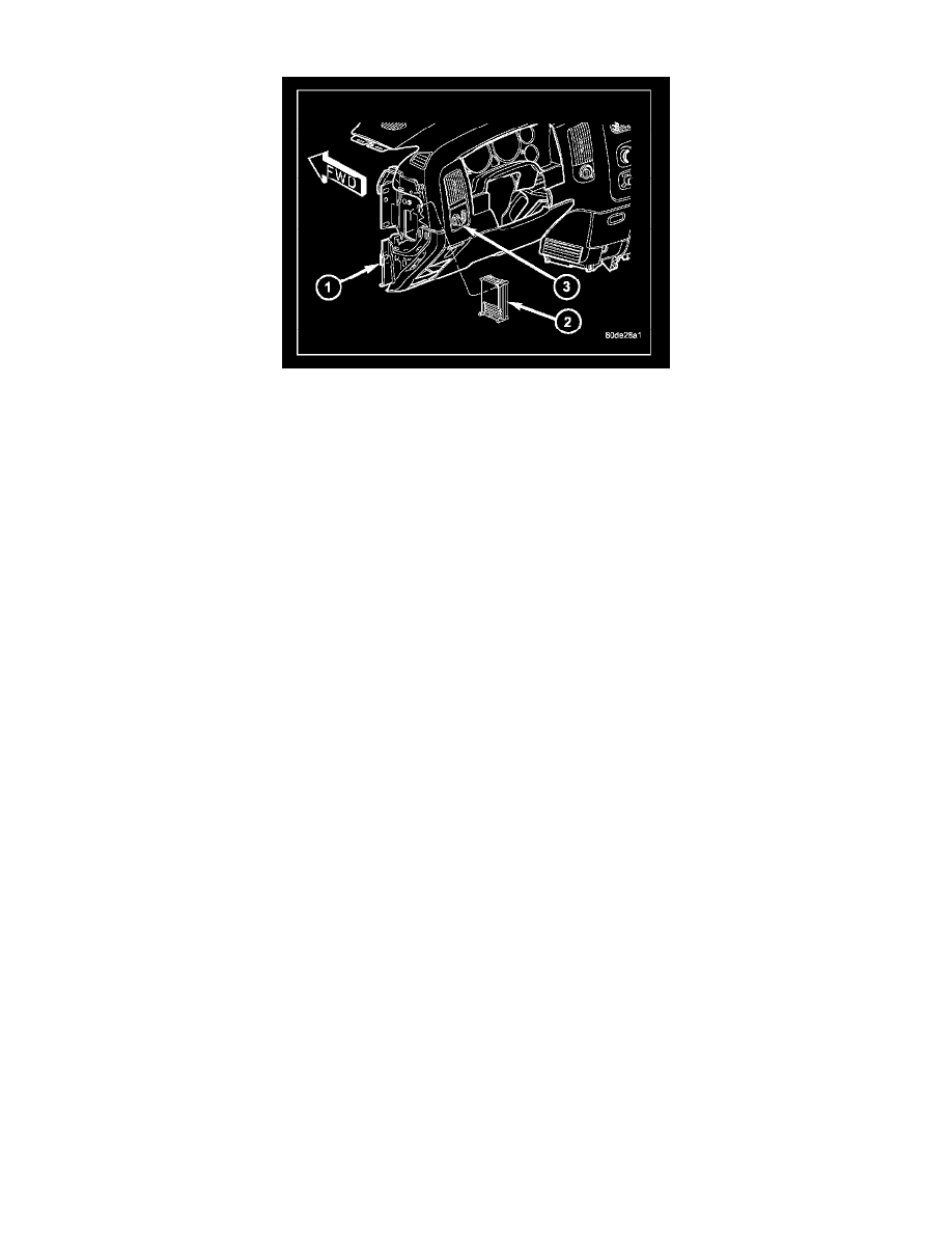
The Transfer Case Control Module (TCCM) (2) is a microprocessor-based assembly, controlling the 4X4 transfer case shift functions via the actuation of
a shift motor and utilizing the feedback of a mode sensor assembly. Communication is via the PCI serial bus. Inputs include user selectable 4X4 modes
that include 2WD, AWD, 4HI, 4LO, and Neutral. The logic and driver circuitry is contained in a molded plastic housing with an embedded heat-sink and
is located behind the left side of the lower instrument panel (1).
The Transfer Case Control Module (TCCM) utilizes the input from the transfer case mounted mode sensor, the instrument panel mounted selector
switch, and the following information from the vehicle's PCI serial bus to determine if a shift is allowed.
-
Engine RPM and Vehicle Speed
-
Diagnostic Requests
-
Manual Transmission and Brake Applied
-
PRNDL
-
Ignition Status
-
ABS Messages
Once the TCCM determines that a requested shift is allowed, it actuates the bi-directional shift motor as necessary to achieve the desired transfer case
operating mode. The TCCM also monitors the mode sensor while controlling the shift motor to determine the status of the shift attempt.
Several items can cause the requested shift not to be completed. If the TCCM has recognized a fault (DTC) of some variety, it will begin operation in
one of four Functionality Levels. These levels are:
-
Level Zero - Normal Operation.
-
Level One - Only Mode Shifts Are Allowed.
-
Level Two - Only Mode Shifts and Shifts Into LOW Are Allowed (No Neutral Shifts Are Allowed).
-
Level Three - No Shifts Are Allowed
The TCCM can also be operating in one of three possible power modes. These power modes are:
-
Full Power Mode is the normal operational mode of the module. This mode is achieved by normal PCI bus traffic being present and the ignition
being in the RUN position.
-
Reduced Power Mode will be entered when the ignition has been powered off. In this state, the module will shut down power supplied to external
devices, and to electronic interface inputs and outputs. From this state the module can enter either Sleep Mode or Full Power Mode. To enter this
mode, the module must receive an ignition message denoting that the ignition is off, or not receive any messages for 5 ± 0.5 seconds. To exit this
mode, the module must receive one ignition message that denotes that the ignition is in the RUN position.
-
Sleep Mode will be entered, from the Reduced Power Mode, when no PCI traffic has been sensed for 20 ± 1 seconds. If during Sleep Mode the
module detects PCI bus traffic, it will revert to the Reduced Power mode while monitoring for ignition messages. It will remain in this state as long
as there is traffic other than run or start messages, and will return to Sleep mode if the bus goes without traffic for 20 ± 1 seconds.
SHIFT REQUIREMENTS
If the TCCM is in full power mode and at functionality level zero, it uses the following criteria to determine if a shift is allowed.
If any of the driver controllable conditions are not met once the shift request is recognized, the TCCM will solidly illuminate the source position's LED
and flash the desired position's LED for all shifts except NEUTRAL. The NEUTRAL shift LED strategy will be discussed later.
Mode shifts will be allowed regardless of transmission gear or vehicle speed, whenever the following conditions are met:
-
Front and rear wheel speed are within 21 km/hr (13 mph).
-
A change in the Selector switch state indicates that a mode shift has been requested.
-
A valid mode sensor signal is being sensed by the TCCM.