
RAM 1500 Truck 4WD V8-5.9L VIN Z (2002)
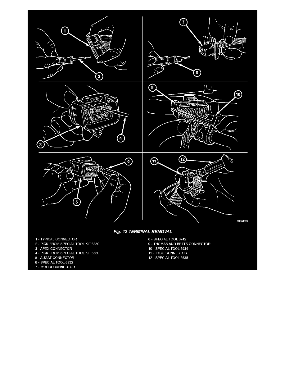
Fig. 12 Terminal Removal
6. Position the connector locking finger away from the terminal using the proper special tool. Pull on the wire to remove the terminal from the
connector (Fig. 12).
INSTALLATION
1. Insert the removed terminal in the same cavity on the repair connector.
2. Repeat steps for each terminal in the connector, being sure that all wires are inserted into the proper cavities. For additional connector pin-out
identification, refer to the wiring diagrams.
3. When the connector is re-assembled, the secondary terminal lock must be placed in the locked position to prevent terminal push out.
4. Replace dress cover (if applicable).
5. Connect connector to its mating half/component.
6. Connect battery and test all affected systems.
Diode Replacement
REMOVAL