
RAM 1500 Van V6-3.9L VIN X (1997)
Oxygen Sensor: Description and Operation
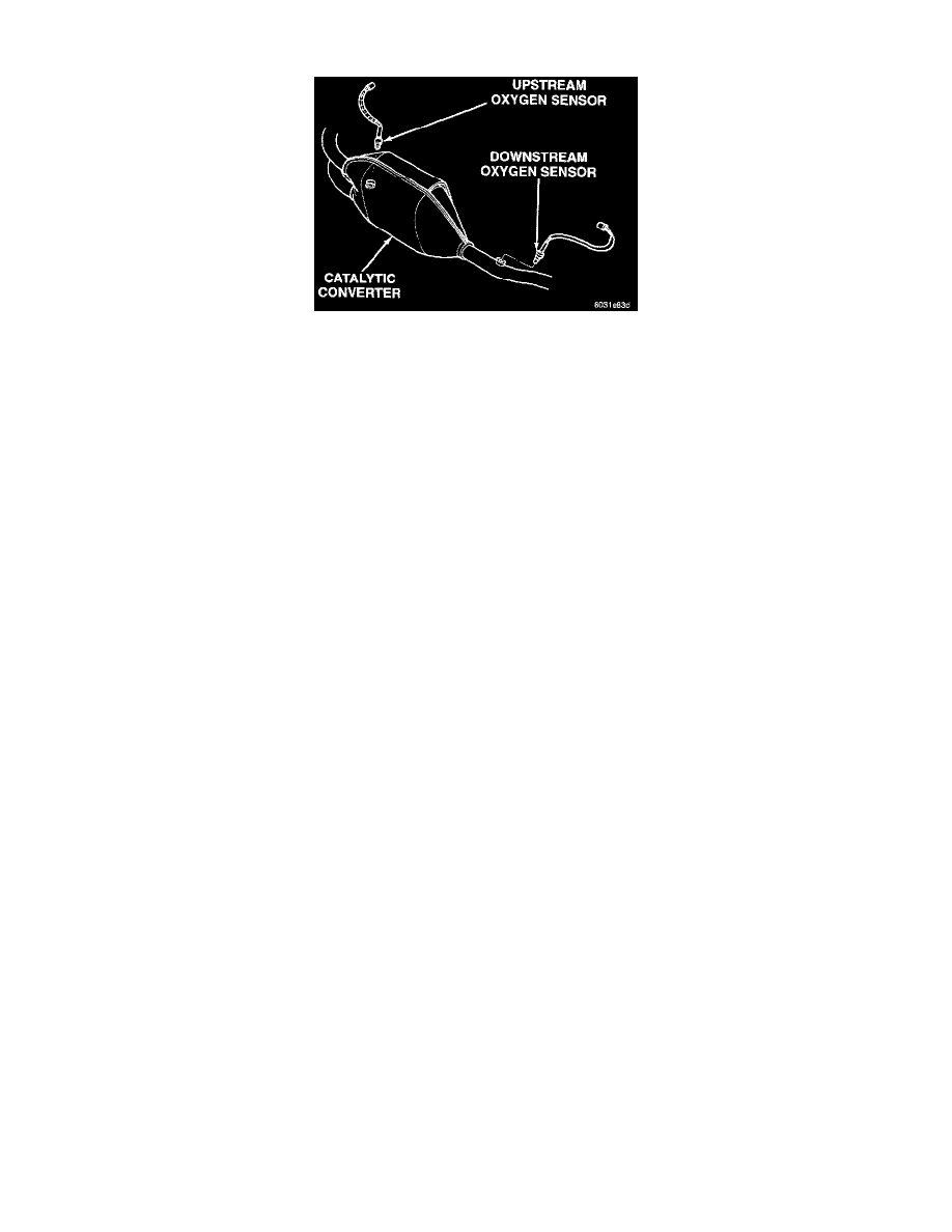
Fig 6 Heated Oxygen Sensors
HEATED OXYGEN SENSOR (O2S)-JTEC INPUT
Two heated 025 sensors are used. The sensors produce voltages from 0 to 1 volt, depending upon the oxygen content of the exhaust gas in the
exhaust manifold. When a large amount of oxygen is present (caused by a lean air/fuel mixture), the sensors produces a low voltage. When there is
a lesser amount present (rich air/fuel mixture) it produces a higher voltage. By monitoring the oxygen content and converting it to electrical
voltage, the sensors act as a rich-lean switch.
The oxygen sensors are equipped with a heating element that keeps the sensors at proper operating temperature during all operating modes.
Maintaining correct sensor temperature at all times allows the system to enter into closed loop operation sooner. Also, it allows the system to
remain in closed loop operation during periods of extended idle.
In Closed Loop operation, the JTEC monitors the O2S sensor input (along with other inputs) and adjusts the injector pulse width accordingly
During Open Loop operation, the JTEC ignores the O2 sensor input. The JTEC adjusts injector pulse width based on preprogrammed (fixed)
values and inputs from other sensors.
The Automatic Shutdown (ASD) relay supplies battery voltage to both the upstream and downstream heated oxygen sensors. The oxygen sensors
are equipped with a heating element. The heating elements reduce the time required for the sensors to reach operating temperature.
UPSTREAM HEATED OXYGEN SENSOR
The upstream O2S sensor is located in the inlet end of the catalytic converter (Fig. 6). It provides an input voltage to the JTEC. The input tells the
JTEC the oxygen content of the exhaust gas. The JTEC uses this information to fine tune the air/fuel ratio by adjusting injector pulse width.
DOWNSTREAM HEATED OXYGEN SENSOR
The downstream heated oxygen sensor threads into the outlet end of the catalytic convertor (Fig. 6). The downstream heated oxygen sensor input
is used to detect catalytic convertor deterioration. As the convertor deteriorates, the input from the downstream sensor begins to match the
upstream sensor input except for a slight time delay. By comparing the downstream heated oxygen sensor input to the input from the upstream
sensor, the JTEC calculates catalytic convertor efficiency.
When the catalytic converter efficiency drops below emission standards, the JTEC stores a diagnostic trouble code and illuminates the
Malfunction Indicator Lamp (MIL). For more information, refer to Group 25, Emission Control Systems.
CIRCUIT OPERATION
When the Automatic Shut Down (ASD) relay contacts CLOSE, they connect circuits A14 and A142. Circuit A142 splices to supply voltage to the
heated oxygen sensors.
Circuit K241 delivers the signal from the upstream heated oxygen sensor to the PCM. Circuit K241 connects to cavity A24 of the Powertrain
Control Module (PCM).
Circuit K341 delivers the signal from the downstream heated oxygen sensor and connects to cavity A25 of the PCM.
The PCM provides a ground for the heated oxygen sensor signals (circuits K241 and K341) through circuit K4. Circuit K4 connects to cavity A4
of the PCM connector.
Circuit Z1 provides a ground for the heater circuit in the sensors.