
RAM 1500 Van V6-3.9L VIN X (1997)
Crankshaft Position Sensor: Description and Operation
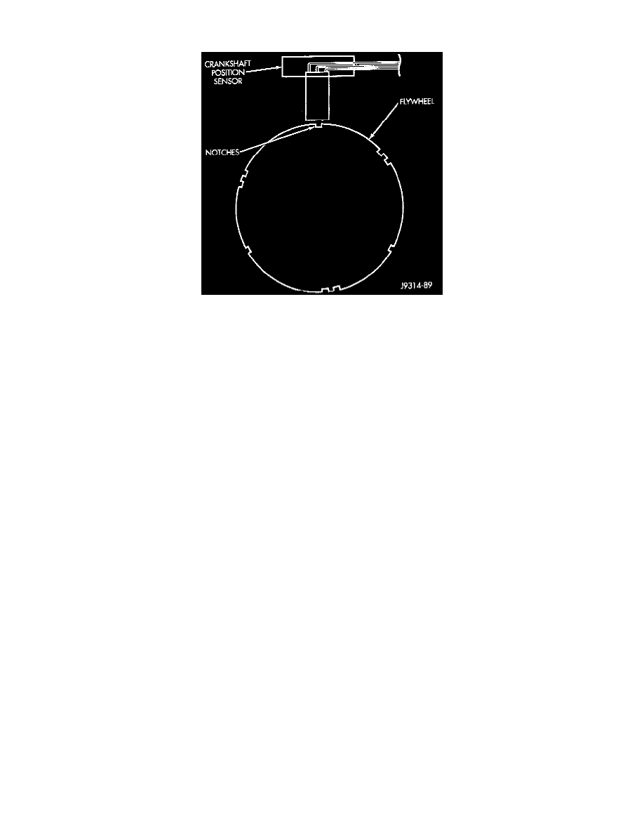
Fig. 4 Sensor Operation
DESCRIPTION
The sensor is a hall effect device combined with an internal magnet. It is also sensitive to steel within a certain distance from it.
The flywheel/drive plate has groups of notches at its outer edge. there are three sets of double notches and three sets of single notches.
The notches cause a pulse to be generated when they pass under the sensor. The pulses are the input to the JTEC.
OPERATION
Engine speed and crankshaft position are provided through the crankshaft position sensor The sensor generates pulses that are the input sent to the
Jeep/Truck Engine Controller (JTEC). The JTEC interprets the sensor input to determine the crankshaft position. The JTEC then uses this
position, along with other inputs, to determine injector sequence and ignition timing.
NOTE: The engine will not operate if the JTEC does not receive a crankshaft position sensor input.
CIRCUIT OPERATION
The Powertrain Control Module (PCM) supplies 5 volts to the crankshaft position sensor on circuit K6. Circuit K6 connects to cavity A17 of the
PCM.
The PCM receives the crankshaft position sensor signal on circuit K24. Circuit K24 connects to cavity A8 of the PCM.
The PCM provides a ground for the crankshaft position sensor (circuit K24) through circuit K4. Circuit K4 connects to cavity A4 of the PCM
connector.