
RAM 1500 Van V8-5.2L CNG VIN T (1999)
17.
Mark the fuel line fitting as shown in Figure 12 and then disconnect the inboard fuel cylinder-to-manual shut off valve fuel line from the inboard
fuel cylinder (Figure 13).
18.
Remove the manual shut off valve mounting nut (Figure 13). Move the manual shut off valve up to allow access to the inboard fuel cylinder
mounting strap nut.
19.
Remove the rear inboard cylinder mounting strap. Set the strap aside for return to the Warranty Material Return Center.
20.
Install the other provided fuel cylinder mounting strap. Evenly tighten the two strap mounting nuts to 180 in-lbs (20 N.m). Do NOT overtighten
and do NOT retighten the first nut after the second nut has been tightened.
21.
Raise the fuel cylinder/carrier assembly back into position. Loosely attach all fuel lines.
22.
Install the outboard side fuel cylinder/carrier mounting bolts and nuts (Figure 11). Tighten the bolts to 80 ft-lbs (108 N.m). Tighten the nuts to 70
ft-lbs (95 N.m).
23.
Remove the lifting device.
24.
Install the inboard side fuel cylinder/carrier mounting bolts (Figure 11). Tighten the bolts to 80 ft-lbs (108 N.m).
25.
Reinstall the manual shut off valve (Figure 13) Torque the mounting nut to 190 in-lbs (21.5 Nm).
26.
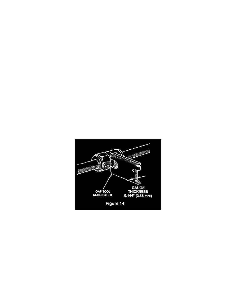
Connect the inboard fuel cylinder-to-manual shut off valve fuel line to the inboard fuel cylinder (Figure 13). Tighten the fitting until the mark is
back in its original position (Figure 12) and then tighten it an additional 1/12 turn. Check the fitting gap with the Go No-Go gauge tool (Figure
14). If the Go No-Go gauge fits in the gap, tighten the fitting slowly until the tool will not fit in the gap.
NOTE:
Special Go No-Go gauge CNG fitting tools for Parker brand tube fittings are available from a local Tube Fitting supplier.
27.
Connect the rear fuel cylinder line to the tee located between the rear end of the fuel cylinders (Figure 13). Tighten the fitting until the mark is
back in its original position (Figure 12) and then tighten it an additional 1/12 turn. Check the fitting gap with the Go No-Go gauge tool (Figure
14). If the Go No-Go gauge fits in the gap, tighten the fitting slowly until the tool will not fit in the gap.
28.
Connect the fuel filler line to the check valve located between the rear end of the fuel cylinders (Figure 13). Tighten the fitting until the mark is
back in its original position (Figure 12) and then tighten it an additional 1/12 turn. Check the fitting gap with the Go No-Go gauge tool (Figure
14). If the Go No-Go gauge fits in the gap, tighten the fitting slowly until the tool will not fit in the gap.
29.
Connect the side cylinder crossover tube and filler tube brackets to the vehicle crossmember (Figure 13).
30. Install the manual shut-off valve handle extension (Figure 13)
31
Connect the coolant line to the mounting bracket between the front end of the fuel cylinders (Figure 11)
32.
Slowly open the fuel control valve on each of the four (4) fuel cylinders to equalize the pressure~ After the pressure has equalized, fully open the
fuel control valve on each of the four (4) fuel cylinders (Figure 1).
33
Check all fuel line connections for leaks using a soapy water solution. Tighten the fuel line connections as necessary.