
RAM 1500 Van V8-5.2L VIN Y (1999)
11. Remove the snap ring that secures the clutch field coil assembly to the compressor front housing.
12. Remove the clutch field coil assembly from the compressor front housing
INSPECTION
Examine the friction surfaces of the clutch pulley and the front plate for wear. The pulley and front plate should be replaced if there is excessive
wear or scoring.
If the friction surfaces are oily, inspect the shaft and nose area of the compressor for oil. If excessive oil is present, the shaft seal is leaking and the
compressor must be replaced.
Check the clutch pulley bearing for roughness or excessive leakage of grease. Replace the bearing, if required.
INSTALLATION
1. Position the back of the clutch field coil against the compressor front housing. Be certain that the locating pin on the back of the coil lines up with
the indentation on the compressor front housing. This ensures the proper orientation of the coil and the wire harness.
2. Install the clutch field coil snap ring (bevel side outward) with snap ring pliers. Be certain that the snap ring is properly seated into the groove.
CAUTION: If the snap ring is not fully seated in the groove it will vibrate out, resulting in a clutch failure and severe damage to the front housing
of the compressor.
3. Install the clutch coil lead wire harness retaining clip on the compressor front housing and tighten the retaining screw.
4. Plug in the compressor clutch wire harness connectors to the thermal limiter switch.
5. Position the clutch pulley assembly onto the compressor.
CAUTION: Do not mar or contaminate the clutch pulley friction surface.
6. Install the clutch pulley assembly snap ring (bevel side outward) with snap ring pliers. Be certain that the snap ring is properly seated in the
groove.
7. Place a trial stack of shims, 2.54 mm (0.10 in.) thick, on the compressor shaft.
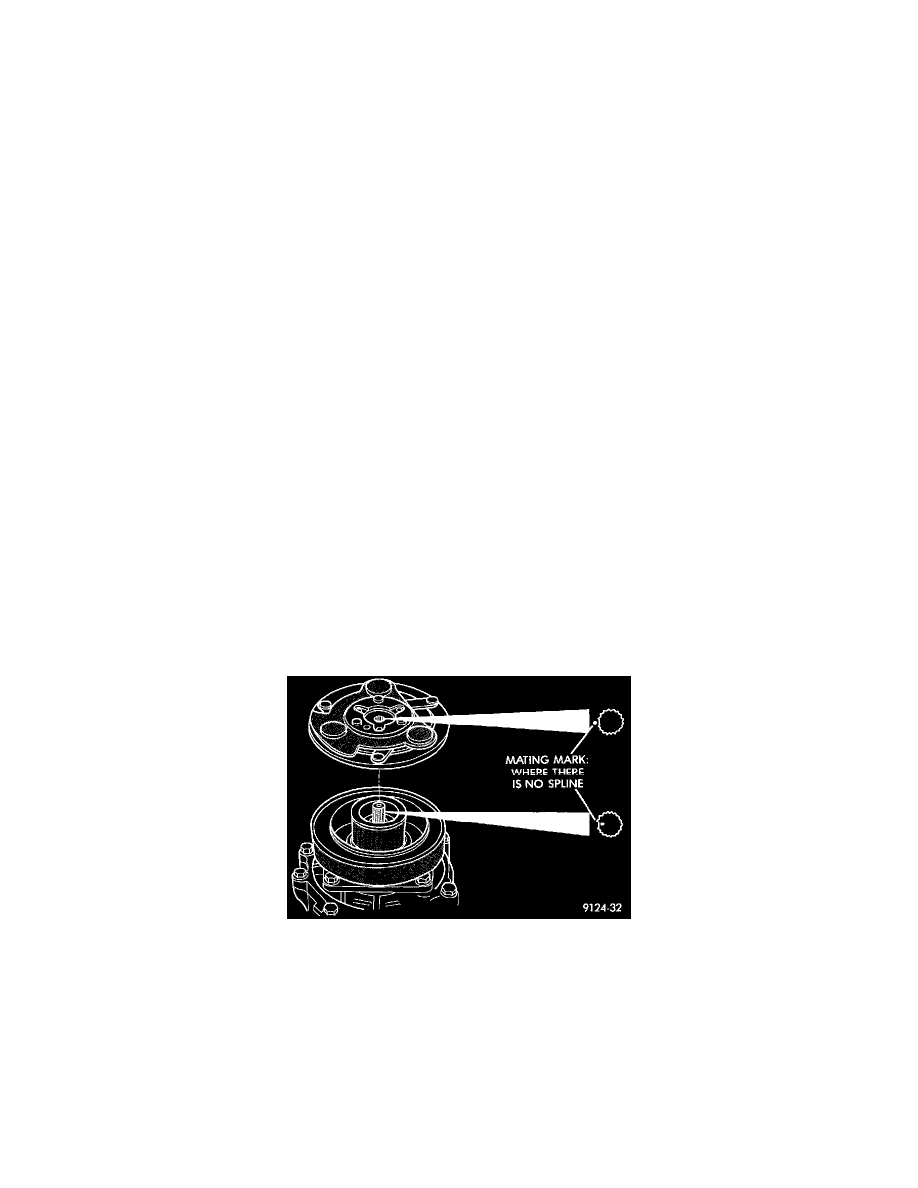
Aligning Clutch Plate Splices
8. Note the machined mating splines on the compressor shaft and in the clutch plate hub.
9. Align the mating splines and install the clutch plate on the compressor shaft.
10. Install the external front rotor snap ring with snap ring pliers. The bevel side of the snap ring must be facing outward. Press the snap ring to make
sure it is properly seated in the groove.