
RAM 1500 Van V8-5.9L VIN Z LDC (2001)
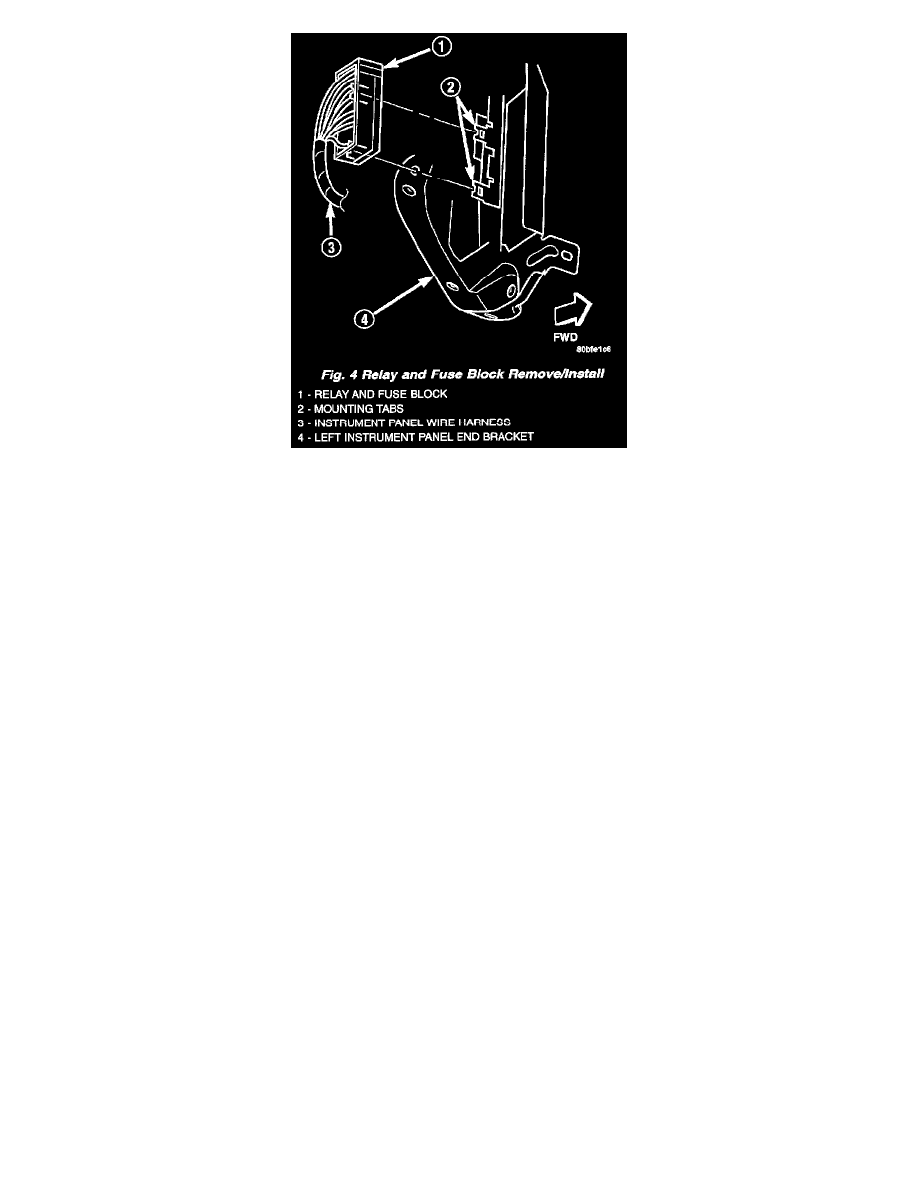
Fig. 4 Relay And Fuse Block Remove/Install
7. Disengage the relay and fuse block from the two mounting tabs on the inboard side of the left instrument panel end bracket (Fig. 4).
8. Remove the fuseblock module, the relay and fuse block and the instrument panel wire harness from the instrument panel as a unit.
INSTALLATION
The fuseblock module is serviced as a unit with the instrument panel wire harness. If any internal circuit of the fuseblock module or the fuseblock
module housing is faulty or damaged, the entire fuseblock module and instrument panel wire harness unit must be replaced.
WARNING: ON VEHICLES EQUIPPED WITH AIRBAGS, DISABLE THE AIRBAG SYSTEM BEFORE ATTEMPTING ANY
STEERING WHEEL, STEERING COLUMN, OR INSTRUMENT PANEL COMPONENT DIAGNOSIS OR SERVICE. DISCONNECT
AND ISOLATE THE BATTERY NEGATIVE (GROUND) CABLE, THEN WAIT TWO MINUTES FOR THE AIRBAG SYSTEM
CAPACITOR TO DISCHARGE BEFORE PERFORMING FURTHER DIAGNOSIS OR SERVICE. THIS IS THE ONLY SURE WAY TO
DISABLE THE AIRBAG SYSTEM. FAILURE TO TAKE THE PROPER PRECAUTIONS COULD RESULT IN ACCIDENTAL AIRBAG
DEPLOYMENT AND POSSIBLE PERSONAL INJURY.
NOTE: If the fuseblock module and the relay and fuse block are being replaced with new units, be certain to transfer each of the fuses, circuit
breakers and relays in the faulty units that have not been included with the replacement units to the proper cavities of the replacement units. Refer to
Fuse/Fuse Block for the location of complete circuit diagrams and cavity assignments for the fuseblock module and the relay and fuse block.
1. Position the fuseblock module, the relay and fuse block and the instrument panel wire harness to the instrument panel as a unit.
2. Engage the relay and fuse block onto the two mounting tabs on the inboard side of the left instrument panel end bracket.
3. From the left outboard end of the instrument panel, install and tighten the two screws that secure the fuseblock module to the left instrument panel
end bracket. Tighten the screws to 3.4 Nm (30 in. lbs.).
4. Engage each of the retainers that secure the instrument panel wire harness to the instrument panel armature. Refer to Connector Locations in
Wiring Diagrams for the location of more information on the instrument panel wire harness retainer locations.
5. Install all of the fasteners that secure each of the instrument panel wire harness ground eyelets to the instrument panel armature. Refer to
Connector Locations in Wiring Diagrams for the location of more information on the ground eyelet locations.
6. Reconnect each of the instrument panel wire harness connectors. Refer to Connector Locations in Wiring Diagrams for the location of more
information on the instrument panel wire harness connector locations.
7. Install the instrument panel assembly into the vehicle. Refer to Instrument Panel Assembly for the location of the proper instrument panel
installation procedures.
8. Reconnect the battery negative cable.