
RAM 1500 Van V8-5.9L VIN Z LDC (2001)
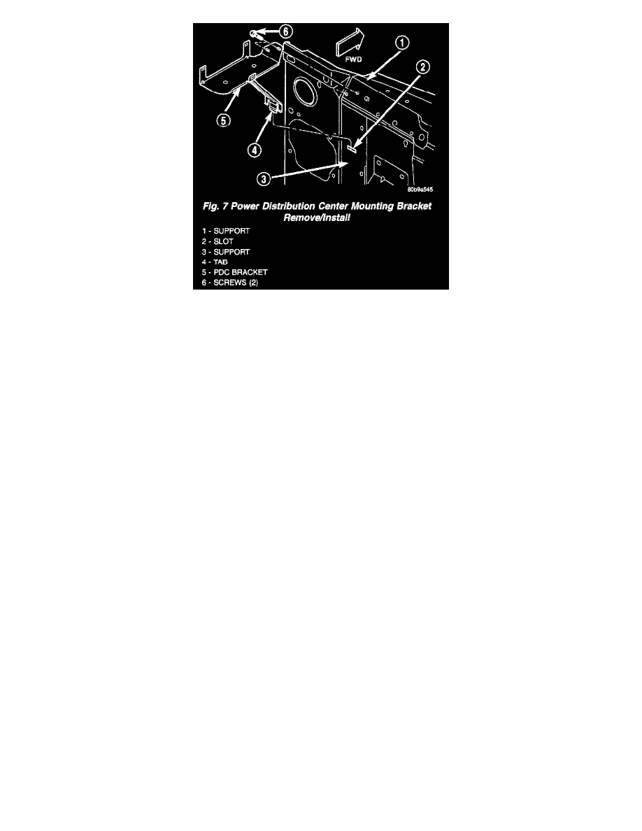
Fig. 7 Power Distribution Center Mounting Bracket Remove/Install
10. Remove the two screws that secure the PDC mounting bracket to the radiator grille support (Fig. 7).
11. Disengage the tab on the PDC mounting bracket brace from the slot in the left headlamp support panel.
12. Remove the PDC mounting bracket from the engine compartment.
INSTALLATION
The Power Distribution Center (PDC) is serviced as a unit with the headlamp and dash wire harness. If any internal circuit of the PDC or the PDC
housing is faulty or damaged, the entire PDC and headlamp and dash wire harness unit must be replaced.
NOTE: If the PDC is being replaced with a new unit, be certain to transfer each of the blade-type fuses, cartridge fuses and relays from the faulty
PDC to the proper cavities of the replacement PDC. Refer to Power Distribution for the location of complete PDC circuit diagrams and cavity
assignments.
1. Position the PDC mounting bracket into the engine compartment.
2. Engage the tab on the PDC mounting bracket brace with the slot in the left headlamp support panel.
3. Install and tighten the two screws that secure the PDC mounting bracket to the radiator grille support. Tighten the screws to 10.7 Nm (95 in. lbs.).
4. Position the PDC and the headlamp and dash wire harness unit in the engine compartment.
5. Engage the PDC onto the mounting bracket.
6. Install the eyelet of the battery positive cable take out onto the inboard B(+) terminal stud in the PDC.
CAUTION: Be certain that both high current cable connections to the B(+) terminal studs in the Power Distribution Center (PDC) are properly
tightened. Improper tightening of these connections can result in improper vehicle electrical system operation and/or damage to vehicle electrical
system components.
7. Install and tighten the nut that secures the eyelet of the battery positive cable take out to the inboard B(+) terminal stud in the PDC. Tighten the nut
to 11.8 Nm (105 in. lbs.).
8. Install the eyelet of the engine wire harness generator output take out onto the outboard B(+) terminal stud in the PDC.
9. Install and tighten the nut that secures the eyelet of the engine wire harness generator output take out to the outboard B(+) terminal stud in the PDC
. Tighten the nut to 8.4 Nm (75 in. lbs.).
10. Install and latch the cover onto the PDC.
11. Engage each of the retainers that secure the headlamp and dash wire harness to the vehicle body and chassis components. Refer to Connector
Locations in Wiring Diagrams for the location of more information on the headlamp and dash wire harness retainer locations.
12. Install all of the fasteners that secure each of the headlamp and dash wire harness ground eyelets to the vehicle body and chassis components.
Refer to Connector Locations in Wiring Diagrams for the location of more information on the ground eyelet locations.
13. Reconnect each of the headlamp and dash wire harness connectors. Refer to Connector Locations in Wiring Diagrams for the location of more
information on the headlamp and dash wire harness connector locations.
14. Reconnect the battery negative cable.