
RAM 1500 Van V8-5.9L VIN Z LDC (2001)
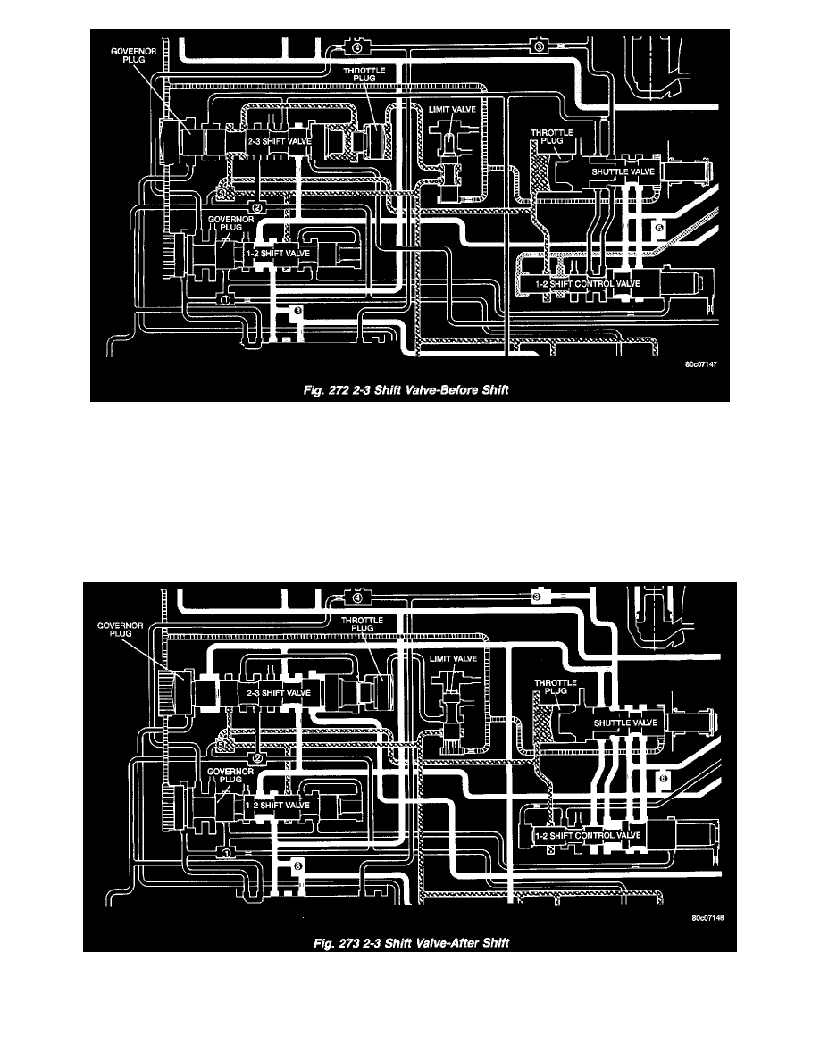
The 2-3 shift valve mechanism (Fig. 272) consists of the 2-3 shift valve, governor plug and spring, and a throttle plug. After the 1-2 shift valve has
completed its operation and applied the front band, line pressure is directed to the 2-3 shift valve through the connecting passages from the 1-2 shift
valve. The line pressure will then dead end at land #2 until the 2-3 valve is ready to make its shift. Now that the vehicle is in motion and under
acceleration, there is throttle pressure being applied to the spring side of the valve and between lands #3 and #4.
As vehicle speed increases, governor pressure increases proportionately, until it becomes great enough to overcome the combined throttle and spring
pressure on the right side of the valve. Since the throttle pressure end of the 2-3 shift valve is larger in diameter than the 1-2 shift valve, the 2-3 shift
will always happen at a greater speed than the 1-2 shift. When this happens, the governor plug is forced against the shift valve moving it to the right.
The shift valve causes land #4 to close the passage supplying throttle pressure to the 2-3 shift valve. Without throttle pressure present in the circuit
now, the governor plug will push the valve over far enough to bottom the valve in its bore. This allows land #2 to direct line pressure to the front
clutch.
After the shift (Fig. 273), line pressure is directed to the land between the shift valve and the governor plug, and to the release side of the kickdown
servo.
This releases the front band and applies the front clutch, shifting into third gear or direct drive. The rear clutch remains applied, as it has been in the
other gears. During a manual "1" or manual "2" gear selection, line pressure is sent between the two lands of the 2-3 governor plug. This line pressure