
RAM 1500 Van V8-5.9L VIN Z LDC (2001)
Wiper Relay: Testing and Inspection
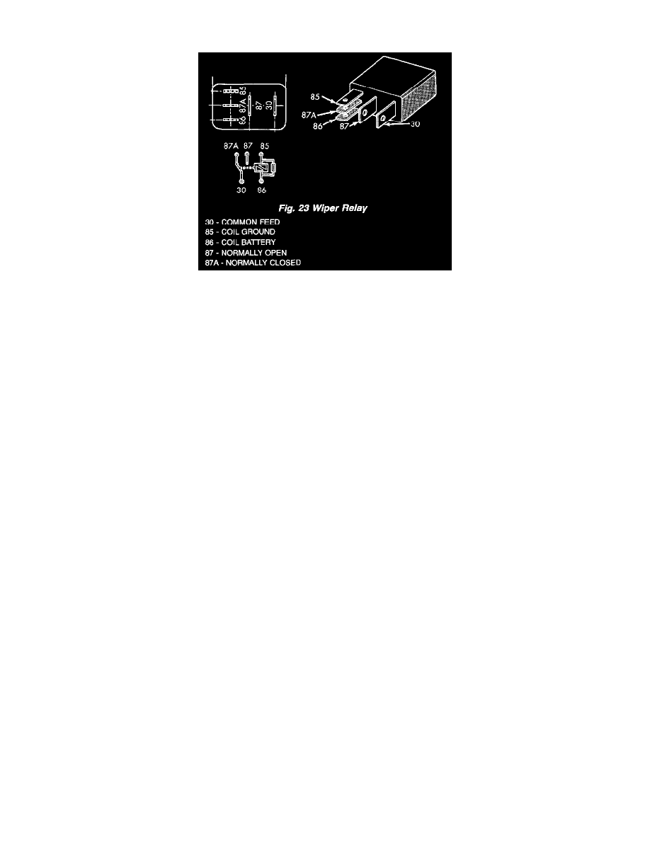
Fig. 23 Wiper Relay
The wiper relay (or intermittent wipe relay is located in a dedicated connector on a take out of the instrument panel wire harness and is taped back to the
harness on the instrument panel cross body structural support above the glove box opening in the passenger compartment.
WARNING: ON VEHICLES EQUIPPED WITH AIRBAGS, DISABLE THE AIRBAG SYSTEM BEFORE ATTEMPTING ANY STEERING
WHEEL, STEERING COLUMN, SEAT BELT TENSIONER, OR INSTRUMENT PANEL COMPONENT DIAGNOSIS OR SERVICE.
DISCONNECT AND ISOLATE THE BATTERY NEGATIVE (GROUND) CABLE, THEN WAIT TWO MINUTES FOR THE AIRBAG
SYSTEM CAPACITOR TO DISCHARGE BEFORE PERFORMING FURTHER DIAGNOSIS OR SERVICE. THIS IS THE ONLY SURE
WAY TO DISABLE THE AIRBAG SYSTEM. FAILURE TO TAKE THE PROPER PRECAUTIONS COULD RESULT IN ACCIDENTAL
AIRBAG DEPLOYMENT AND POSSIBLE PERSONAL INJURY.
1. Remove the wiper relay from the instrument panel wire harness connector. (Refer to WIPERS/WASHERS/WIPER RELAY - REMOVAL).
2. A relay in the de-energized position should have continuity between terminals 87A and 30, and no continuity between terminals 87 and 30. If OK,
go to Step 3. If not OK, replace the faulty relay.
3. Resistance between terminals 85 and 86 (electromagnet) should be 75 ± 5 ohms. If OK, go to Step 4. If not OK, replace the faulty relay.
4. Connect a battery to terminals 85 and 86. There should now be continuity between terminals 30 and 87, and no continuity between terminals 87A
and 30. If OK, test the relay input and output circuits. Refer to RELAY CIRCUIT TEST. If not OK, replace the faulty relay.
Relay Circuit Test
1. The relay common feed terminal cavity (30) is connected to the multi-function switch. There should be continuity between the cavity for terminal
30 of the wiper relay in the instrument panel wire harness connector and the wiper relay output circuit cavity of the instrument panel wire harness
connector for the multi-function switch at all times. If OK, go to Step 2. If not OK, repair the wiper relay output circuit between the wiper relay
and the multi-function switch as required.
2. The relay normally closed terminal (87A) is connected to the wiper motor park switch through the wiper motor park switch sense circuit. There
should be continuity between the cavity for terminal 87A of the wiper relay in the instrument panel wire harness connector and the wiper motor
park switch sense circuit cavity of the headlamp and dash wire harness connector for the wiper motor at all times. If OK, go to Step 3. If not OK,
repair the open wiper motor park switch sense circuit between the wiper relay and the wiper motor as required.
3. The relay normally open terminal (87) is connected to a fused ignition switch output (run-acc) fuse in the fuse block through a fused ignition
switch output (run-acc) circuit. There should be battery voltage at the cavity for terminal 87 of the wiper relay in the instrument panel wire harness
connector whenever the ignition switch is in the ON or Accessory positions. If OK, go to Step 4. If not OK, repair the open fused ignition switch
output (run-acc) circuit between the wiper relay and the fuse block as required.
4. The coil ground terminal (85) is connected to a fused ignition switch output (run-acc) fuse in the fuse block through a fused ignition switch output
(run-acc) circuit. There should be battery voltage at the cavity for terminal 85 of the wiper relay in the instrument panel wire harness connector
whenever the ignition switch is in the ON or Accessory positions. If OK, go to Step 5. If not OK, repair the open fused ignition switch output
(run-acc) circuit between the wiper relay and the fuse block as required.
5. The coil battery terminal (86) is connected to the output of the Central Timer Module (CTM) through the wiper relay control circuit. There should
be continuity between the cavity for terminal 86 of the wiper relay in the instrument panel wire harness connector and the wiper relay control
circuit cavity of the instrument panel wire harness connector (Connector C1) for the CTM at all times. If not OK, repair the open wiper relay
control circuit between the wiper relay and the CTM as required.