
RAM 2500 Truck 2WD L6-359 5.9L DSL Turbo VIN D FI (1997)
As the exciter ring passes the tip of the WSS, the magnetic lines of force of the sensor are cut, causing the magnetic field to be moved across the
sensor's windings. This, in turn causes current to flow through the WSS circuit. Every time a tooth of the exciter ring passes the tip of the WSS, an
AC signal is generated. Each AC signal (positive to negative signal or sine-wave) is interpreted by the CAB. It then compares the frequency of the
sine-wave to a time value to calculate vehicle speed. The CAB continues to monitor the frequency to determine a deceleration rate that would
indicate a possible wheel-locking tendency.
TOOTHED RING AND WSS SIGNAL CHARACTERISTICS
The signal strength of any magnetic induction sensor is directly affected by:
^
Magnetic field strength; the stronger the magnetic field, the stronger the signal
^
Number of windings in the sensor; more windings provide a stronger signal
^
Exciter ring speed; the faster the exciter ring rotates, the stronger the signal will be
^
Distance between the exciter ring teeth and WSS; the closer the WSS is to the exciter ring, the stronger the signal will be.
TOOTHED RING TO WSS CLEARANCE
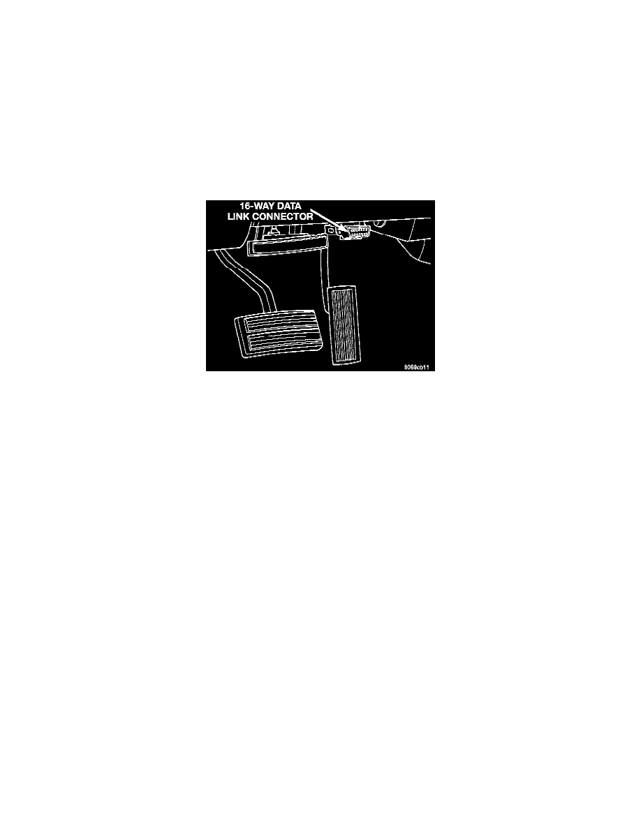
Data Link Connector
The rear WSS is not adjustable. A clearance specification has been established for manufacturing tolerances. If the clearance is not within these
specifications, then either the WSS or other components may be damaged. The clearance between the WSS and the exciter ring is 0.005 - 0.050
inch. The assembly plant performs a "Rolls Test" on every vehicle that leaves the assembly plant. One of the test performed is a test of the WSS.
To properly test the sensor, the assembly plant connects test equipment to the Data Link Connector (DLC). This connector is located to the left of
the steering column and attached to the lower portion of the instrument panel. The rolls test terminal is spliced to the WSS circuit. The vehicle is
then driven on a set of rollers and the WSS output is monitored for proper operation.