
RAM 2500 Truck 2WD L6-359 5.9L DSL Turbo VIN D FI (1997)
11.
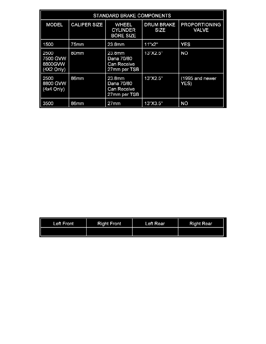
Inspect the combination valve in front of the booster housing to verify that the correct valve has been installed on the vehicle. All Dodge Ram
trucks are equipped with a metering valve and a differential pressure switch located internal to the combination valve. Only some trucks have a
proportioning valve. If the truck has a proportioning valve, it will have a hex visible with a rubber plug over it on the rear side of the combination
valve. Refer to the chart for identifying correct brake components.
12.
Reassemble the rear brakes and install all four tire/wheel assemblies.
Steering and Suspension Inspection
1.
Remove any component on the vehicle that may cause a change in curb height (e.g. snow plow), if possible.
2.
Inspect the condition, and size of all tires. Replace any tire(s) that is/are worn, damaged, or of the incorrect size. Also, verify that all four tires are
of the same brand.
3.
Inflate all tires to the pressure specified in the Tire Inflation Pressure sheet (located in the glove box).
4.
Inspect all wheels to verify that the wheels are of the correct size, offset, and are not bent/damaged. Replace any bent/damaged wheel or wheel(s)
that is/are not of the correct size or do not have the correct offset.
NOTE:
IF VEHICLE IS CURRENTLY EQUIPPED WITH AFTERMARKET TIRE AND WHEEL ASSEMBLIES, INSTALL FACTORY APPROVED
TIRE AND WHEEL ASSEMBLIES BEFORE PERFORMING FURTHER DIAGNOSIS.
5.
Record the vehicle's curb height. Measurement locations can be found using the 1997 Ram Truck Service Manual (Publication Number
81-370-7108), page 2-6.
NOTE:
THE SERVICE MANUAL DOES NOT LIST SPECIFICATIONS FOR CURB HEIGHT. IF A DIFFERENCE OF ONE INCH FROM THE LEFT
CURB HEIGHT TO THE RIGHT CURB HEIGHT IS IDENTIFIED, INSPECT RELATED SUSPENSION COMPONENTS AND REPLACE
ANY DAMAGED COMPONENT AS NECESSARY. REFER TO THE 1997 RAM TRUCK SERVICE MANUAL (PUBLICATION NO.
81-370-7108), GROUP 2 FOR INFORMATION REGARDING SUSPENSION COMPONENT SERVICE.
6.
Inspect the following steering and suspension components for wear and damage. Replace any component that is bent or out of tolerance. Use the
1997 Ram Truck Service Manual (Publication Number 81-370-7108), Groups 2 and 19 for inspection and service procedures.
^
Frame
^
Tie Rod
^
Drag Link
^
Pitman Arm
^
Idler Arm
^
Left Front Upper Suspension Arm Bushings