
RAM 2500 Truck 2WD L6-359 5.9L DSL Turbo VIN D FI (1997)
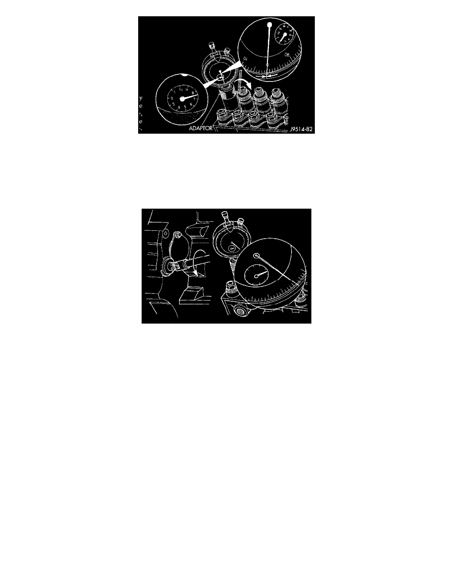
Fig 43 Installing Special Adapter Tool
10. Loosen the set screw on the dial indicator adaptor. Install the dial indicator #6859 and dial indicator tip #6843 into the adapter. Position the dial
indicator to read between 7.0 and 9.0 mm and tighten the set screw. The dial indicator is capable of measuring from 0-20.00 mm lift. The small
inner dial is marked in increments of 1 mm. The large outer dial is marked in increments of 0.01 mm. One revolution of the outer dial is equal to 1
mm. The inner dial only indicates 0-10 mm, but will rotate twice as the indicator goes through the full range.
11. Be sure the timing pin is disengaged before rotating the engine to avoid damage to the timing pin.
Fig 44 Setting Dial Indicator
12. Using the engine barring tool #7471B, rotate the engine in the direction opposite normal direction of engine rotation (counterclockwise from front
of engine) 1/4 turn or until you see the dial indicator reading stop dropping. This is the inner base circle of the injection pump cam. Zero the
indicator and note the reading on the small inner dial.
a. Slowly rotate engine clockwise to TDC. When at TDC, the timing pin should easily push into machined hole in back of camshaft gear. Pull pin
from gear after verifying TDC position.
b. Note the pump lift setting on the dial indicator.
c. Note the injection pump CPL number and "Timing-TDC" specification (in degrees) stamped into the engine data plate. The engine data plate
is located on the left side of the timing gear cover.
d. Refer to the Fuel Injection Pump Plunger Lift charts. The charts contain a nominal timing specification and a pump plunger lift tolerance
specification.
e. If reading on dial indicator, and specification for pump plunger lift match, a fuel timing adjustment will not be necessary. Proceed to Step 26.
f.
If reading and specifications do not match, a fuel timing adjustment will be necessary. Proceed to next step.