
RAM 2500 Truck 2WD L6-5.9L DSL Turbo VIN 7 (2001)
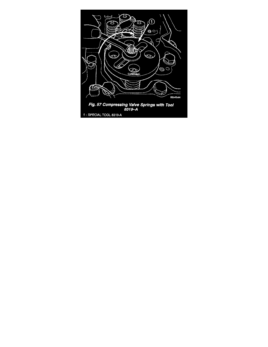
c. Install the top plate, washer, and nut. Using a suitable wrench tighten the nut (clock-wise) (Fig. 57) to compress the valve springs and remove
the collets.
d. Rotate the compressor nut counter-clockwise to relieve tension on springs. Remove spring compressor.
e. Remove and replace retainers, springs, and seals as necessary.
f.
Do not rotate the engine until the springs and retainers are re-installed.
g. Install seals, springs and retainers. Install spring compressor, compress valve springs and install the collets.
h. Release the spring tension and remove the compressor. Verify that the collets are seated by tapping on the valve stem with a plastic hammer.
10. Using the crankshaft barring tool, rotate the engine until the next crankshaft damper paint mark aligns with the mark you placed on the cover. In
this position, cylinders #2 and #5 can be serviced.
11. Repeat the valve spring compressing procedure previously performed and service the retainers, springs, and seals as necessary.
12. Using the crankshaft barring tool, rotate the engine until the next crankshaft damper paint mark aligns with the mark you placed on the cover. In
this position, cylinders #3 and #4 can be serviced.
13. Repeat the spring compressing procedure previously performed and service the retainers, springs, and seals as necessary.
INSTALLATION
1. Install all injector clamps into their original location (Fig. 54). Tighten the hold down bolt to 10 Nm (89 in. lbs.) torque.
2. Lubricate the valve tips and install the crossheads in their original locations.
3. Lubricate the crossheads and push rod sockets and install the rocker arms and pedestals in their original locations (Fig. 53). Tighten bolts to 36
Nm (27 ft. lbs.) torque,
4. Verify valve lash adjustment.
5. Install cylinder head cover and reusable gasket (Fig. 52).
6. Install the accessory drive belt.
7. Connect battery negative cables.