
RAM 2500 Truck 2WD L6-5.9L DSL Turbo VIN 7 (2001)
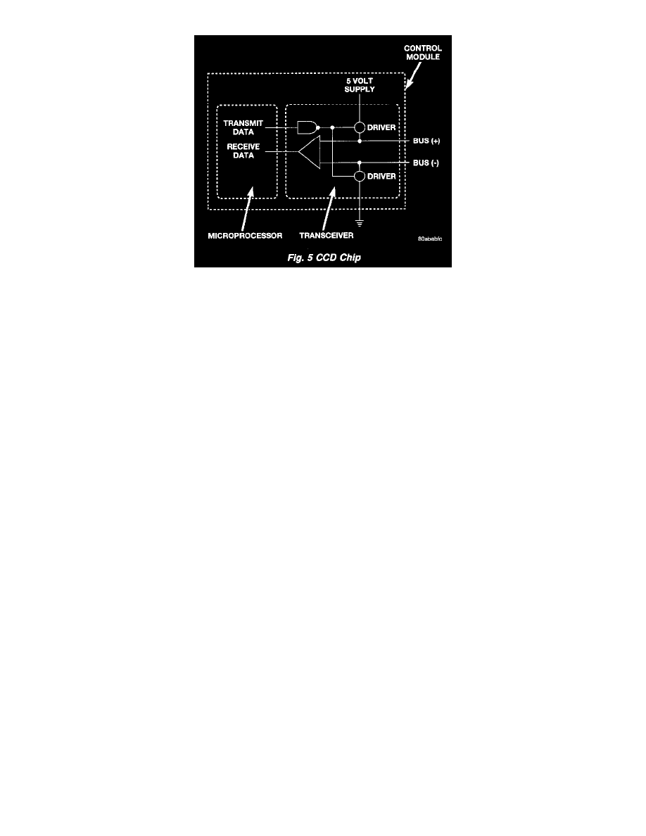
Fig.5 CCD Chip
CCD Chips
In order for an electronic control module to communicate on the CCD data bus, it must have a CCD chip. The CCD chip contains a differential
transmitter/receiver (or transceiver), which is used to send and receive messages. Each module is wired in parallel to the data bus through its CCD
chip.
The differential transceiver sends messages by using two current drivers: one current source driver, and one current sink driver. The current drivers
are matched and allow 0.006 ampere to flow through the data bus circuits. When the transceiver drivers are turned ON, the Bus (+) voltage
increases slightly, and the Bus (-) voltage decreases slightly. By cycling the drivers ON and OFF, the CCD chip causes the voltage on the data bus
circuit to fluctuate to reflect the message.
Once a message is broadcast over the CCD data bus, all electronic control modules on the data bus have the ability to receive it through their CCD
chip. Reception of CCD messages is also carried out by the transceiver in the CCD chip. The transceiver monitors the voltage on the data bus for
any fluctuations. When data bus voltage fluctuations are detected, they are interpreted by the transceiver as binary messages and sent to the
electronic control module's microprocessor.
Bus Bias And Termination
The voltage network used by the CCD data bus to transmit messages requires both bias and termination. At least one electronic control module on
the data bus must provide a voltage source for the CCD data bus network known as bus bias, and there must be at least one bus termination point
for the data bus circuit to be complete. However, while bias and termination are both required for data bus operation, they both do not have to be
within the same electronic control module. The COD data bus is biased to approximately 2.5 volts. With each of the electronic control modules
wired in parallel to the data bus, all modules utilize the same bus bias. Therefore, based upon vehicle options, the data bus can accommodate two
or twenty electronic control modules without affecting bus voltage.