
RAM 2500 Truck 2WD L6-5.9L DSL Turbo VIN 7 (2001)
Valve Lash Limit Chart
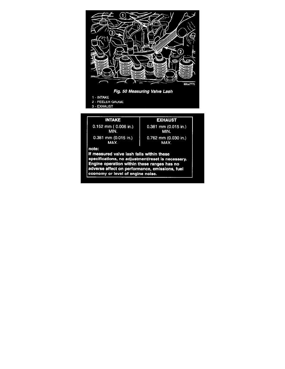
Measure the valve lash by inserting a feeler gauge between the rocker arm socket and crosshead (Fig. 50). Refer to Valve Lash Limit Chart for the
correct specifications.
-
If the measurement falls within the limits, adjustment/resetting is not necessary.
-
If measurement finds the lash outside of the limits, adjustment/resetting is required.
6. If adjustment/resetting is required, loosen the lock nut on rocker arms and turn the adjusting screw until the desired lash is obtained:
INTAKE: 0.254 mm (0.010 inch)
EXHAUST: 0.508 mm (0.020 inch)
Tighten the lock nut to 24 Nm (18 ft. lbs.) and re-check the valve lash.
7. Using the crankshaft barring tool, rotate the crankshaft one revolution (360°) to align the pump gear mark to the 6 o'clock position in relation to
the TDC mark on the gear housing cover (Fig. 49).
8. With the engine in this position (pump gear mark at 6 o'clock), valve lash can be measured at the remaining rocker arms:
-
INTAKE 3-5-6
-
EXHAUST 2-4-6
Use the same method as above for determining whether adjustment is necessary, and adjust those that are found to be outside of the limits.
9. Install the cylinder head cover (Fig. 47).
10. Install the fuel pump gear access cover.
11. Connect the battery negative cables.