
RAM 2500 Truck 2WD L6-5.9L DSL Turbo VIN 7 (2001)
Battery Cable: Description and Operation
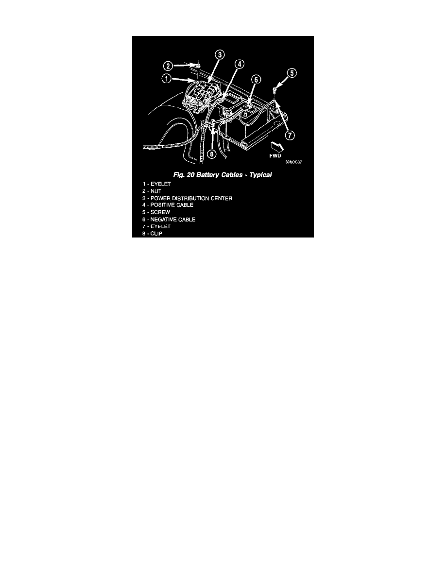
Fig.20 Battery Cables - Typical
The battery cables (Fig. 20) are large gauge, stranded copper wires sheathed within a heavy plastic or synthetic rubber insulating jacket. The wire used in
the battery cables combines excellent flexibility and reliability with high electrical current carrying capacity.
The battery cables cannot be repaired and, if damaged or faulty they must be replaced. Both the battery positive and negative cables are available for
service replacement only as a unit with the battery positive cable wire harness or the battery negative cable wire harness, which may include portions of
the wiring circuits for the generator and other components on some models.
The battery cables connect the battery terminal posts to the vehicle electrical system. These cables also provide a return path for electrical current
generated by the charging system for restoring the voltage potential of the battery. The female battery terminal clamps on the ends of the battery cable
wires provide a strong and reliable connection of the battery cable to the battery terminal posts. The terminal pinch bolts allow the female terminal
clamps to be tightened around the male terminal posts on the top of the battery. The eyelet terminals secured to the ends of the battery cable wires
opposite the female battery terminal clamps provide secure and reliable connection of the battery to the vehicle electrical system.
Diesel engine models feature a clamping type female battery terminal made of soft lead die cast onto one end of the battery cable wire. A square headed
pinch-bolt and hex nut are installed at the open end of the female battery terminal clamp. The pinch-bolt on the left side battery positive cable female
terminal clamp also has a stud extending from the head of the bolt. Large eyelet type terminals are crimped onto the opposite end of the battery cable
wire and then solder-dipped. The battery positive cable wires have a red insulating jacket to provide visual identification and feature a larger female
battery terminal clamp to allow connection to the larger battery positive terminal post. The battery negative cable wires have a black insulating jacket
and a smaller female battery terminal clamp.
The left battery positive cable terminal clamp is die cast onto the ends of two wires. One wire has an eyelet terminal that connects the left battery positive
cable to the B(+) terminal stud of the Power Distribution Center (PDC), and the other wire has an eyelet terminal that connects the left battery positive
cable to the B(+) terminal stud of the engine starter motor solenoid. The right battery positive cable terminal clamp is die cast onto the end of a single
wire. The eyelet terminal on the other end of the right battery positive cable is connected to the stud on the pinch-bolt of the left battery positive cable
terminal clamp. This stud also provides a connection point for the eyelet terminals from the fuel heater relay and intake air heater relay jumper harness
take outs. All of these eyelet terminals are secured to the left battery positive cable terminal clamp pinch-bolt stud with a single hex nut.
The left battery negative cable terminal clamp is die cast onto the ends of two wires. One wire has an eyelet terminal that connects the left battery
negative cable to the vehicle powentrain through a ground screw on the left side of the engine block, below the power steering and vacuum pumps. The
other wire has an eyelet terminal that connects the left battery negative cable to the vehicle body through a ground screw on the left front fender inner
shield, just ahead of the left battery. An additional ground wire with two eyelet terminals is used to provide ground to the vehicle frame. One eyelet
terminal of this ground wire is installed under the nut of the left battery negative cable terminal clamp pinch-bolt, and the other eyelet terminal is secured
with a ground screw to the outer surface of the left frame rail, below the left battery. The right battery negative cable terminal is also die cast onto the
ends of two wires. One wire has an eyelet terminal that connects the right battery negative cable to the vehicle powertrain through a ground screw on the
right side of the engine block, just forward of the right engine mount. The other wire has an eyelet terminal that connects the right battery negative cable
to the vehicle body through a ground screw on the right front fender inner shield, just behind the right battery.